Im not actually sure but i dont think ive seen the values move on the steer setup page when i move the steering sensor arm.
Getting plenty of voltage from 0.2v to 5v when i move the arm but its not registering anywhere
You need a 1K resister when using the ads1115 board. I ran into the same issue and folks helped me. let me find the link to it.
2 Likes
What else can i check or test?
Ive swapped the ads1115 for a new one and still the same problem
Ah ideal. Where do i need to put that?
Im guessing the signal line to num down the voltage to stop the excess range error
chek volts in ads115 when you move the was
I got my WAS to actually function as its suppose to. I wired the ampseal in correlation to that diagram I posted earlier.
pin 1 +5V sensor side #5
pin 2 signal #4
pin 4 - ground #1
I didnt get any response connecting the output wire on the 5v low pin but got a response on the 5v high pin. Using the multi meter (testing ground and pin 2) also showed variations in voltages as the sensor arm was moved. I did notice that the arm needed to be inline towards the plug connection to get it to zero out. Extreme angle from that position resulted in crazy output. My board has the ads1115 installed from jlcpcb so I didnt have to add that. Hopefully adding the resistor will solve your connection issue. Again Im using the land rover RQH100030 sensor. Thank you guys for all your help!
1 Like
Ok ivr done some more testing. When the sensor is set at 2.1v
At the ads1115 in getting VDD and GND 5v
SCL 4.94V
SDA 4.94V
ADDR OV
ALRT 4.97V
A0 0.25V
A1 0V
A2 0V
A3 0V
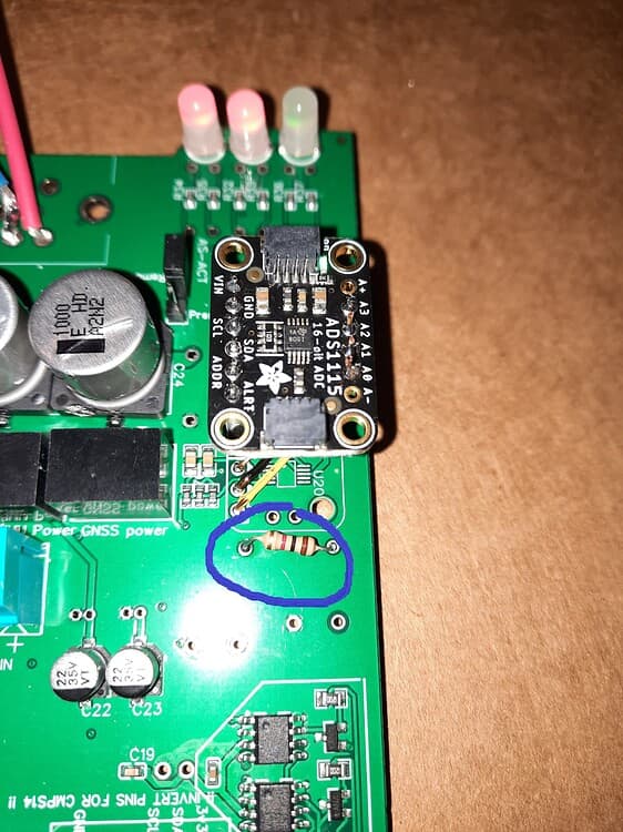
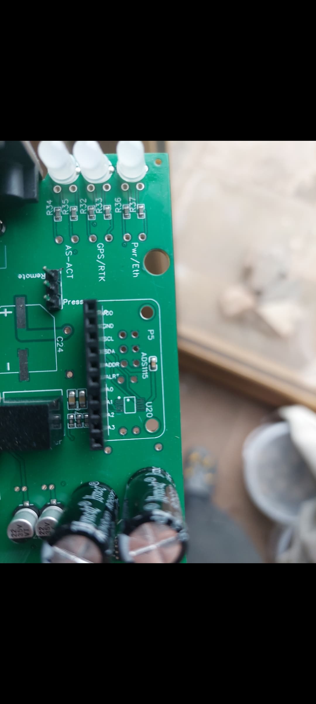
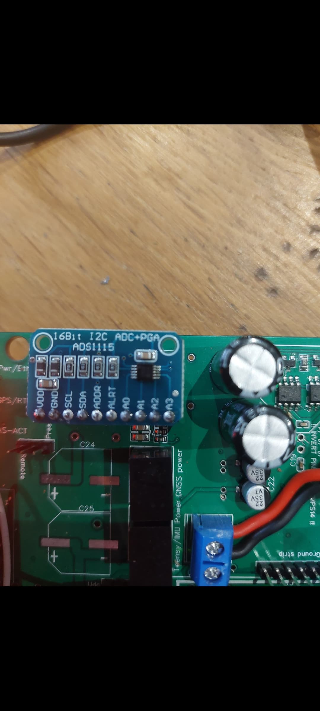
Ive attached a picture of my ads1115 and whats underneath it
and when you move the sensor do you have differnt in A0?
I did try and i thought maybe it was changing but cant be 100% (couldn’t hold the probes and move sensor by myself)
Should i get a range of voltage at A0?
Do i definitely need this 1k resistor fitted with my style of ads1115
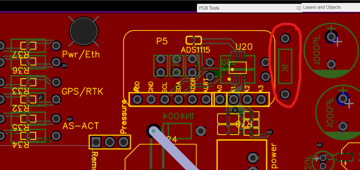
What I learned is that when not using the SMD ads1115 you need the resister. The 2 different ADS1115 boards work exactly the same, just that with the new one you have to wire the 4 pins in the board to the PCB. Without the resister, I believe you would have the same voltage at ampseal pin2 as you would have at one of the holes shown in this picture shown here. The other hole will probably match the ADS1115 A0. Using EasyEDA, you can put your cursor over the pins/holes and see the connections.
1 Like
Thankyou very much. Ive ordered some resistors so I’ll try that and report back
Having an issue getting vehicle settings files to load if anyone on this thread has experience with could you jump over to:
Vehicle settings file setup - Operations/Getting Started - AgOpenGPS
Is the remote/pressure jumper used at all with a steering motor or is that just for hydraulic steering systems?
Solution to my was not zeroing was adding the 1k resistor as mentioned above.
Tested sensor at 2.5 volts now it shows 2.5v on the ads1115 pin A0.
Connected the tablet and reset was, when moving the sensor the wheels on the screen move.
Thanks for the help and responses. (no idea how i find the 'solution tick ) button
What a brilliant community ![]()
On with the project and install
2 Likes
That’s great that your working. I was so happy when Patrick pointed out that problem for me.
1 Like
I was over the moon aswell.
Is there a way of testing the steer motor in simulator mode or do i just need to install it all in the tractor now? Got the was working, got the steer switch wired up and working, green light on the aio is going green for steering module. Can only get the motor to turn with pressing the buttons on the cytron
Use simulation.mode on bench. Make a button or switch connect pwm to motor and your ready to go.