Have you gone through the steer wizard setup to start with to get your basic settings right 1st
I just got everything connected up yesterday but was just looking around in the steer wizard. My steer button works now. Im not sure what all I can set in there as system isnt in tractor yet. Ive spent the last week figuring out how to get the udp network operational.
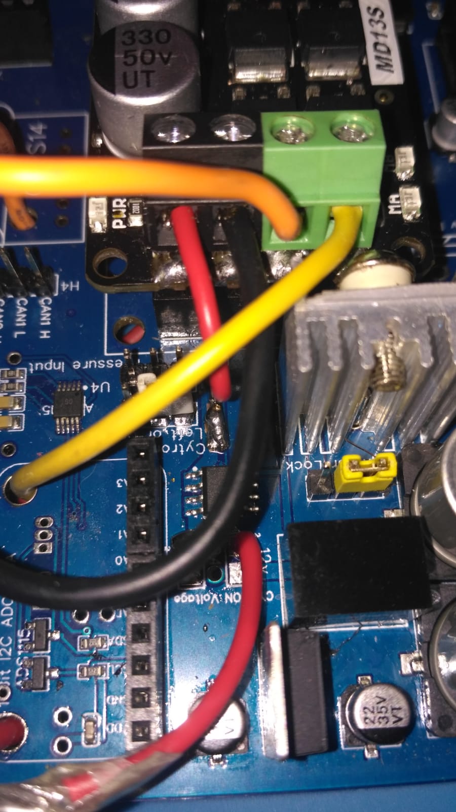
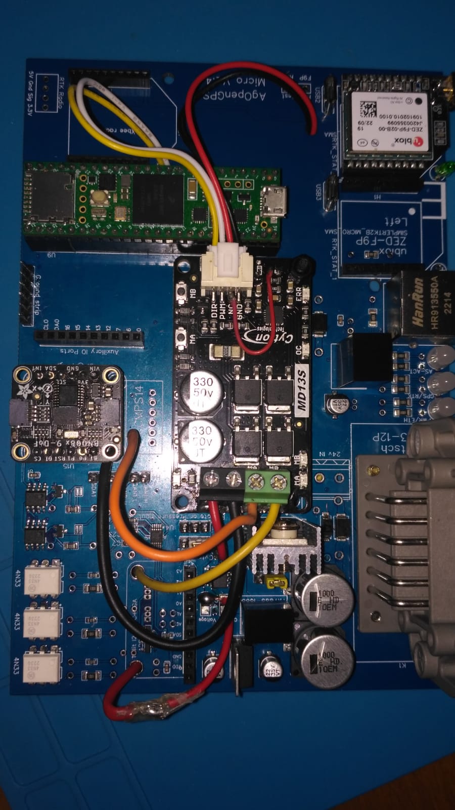
Does the 3 pin header actually do anything as far as input to the pcb or cytron? I’m currently on my first build of this Aio board and I seem to have no power to my cytron. I edge soldered the three pins to the cytron in correspondence to the header. Should I remove them and use the 4 wire plug in order to make it functional? Or do I just need to do the trace mod on the pcb and run a single wire up to the cytron? Thanks for your input
Are you using a Cytron with the free wheel mod? If yes, then you need the 4th connection. Otherwise the three edge connections take care of signaling the Cytron. Of course you need 12-24V and ground at the other end of the Cytron too.
1 Like
I don’t plan to do the free wheel mod as I’m only using the motor as a friction style setup on the steering wheel. I haven’t connected the 24v to the board so maybe that’s why I have no lights or actively on the cytron? This is all on the bench testing prior to installing in my tractor. Thanks for the response. I will connect 24v to it today and further test. Was just curious about that 4th wire from the pcb
If your using the 24v in screw terminals you will also need to solder the 2 24v pads together in front of the cytron
Ok thanks. Will do.
Hello, my intention is to use the automatic deactivation of the motor when I force the steering wheel, I have reinforced the connections to avoid burning the pcb. I connect the cytron directly to the current of the tractor 14.5 volts passing through the current sensor. Everything is correct?
ok I soldered the 24v tabs on the pcb and connected 24v. System is up and running with all modules in green and now have lights on the cytron. Steer motor is connected and operates with the buttons on the cytron. I dont seem to get any respose from the WAS. Is there somewhere i need to configure or connect the WAS or cytron? I will continue to search through past threads. Sorry for the dumb questions.
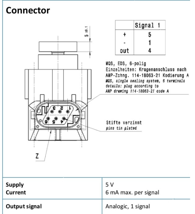
Does the WAS need the ground connected to it? Ampseal wiring diagram shows 4 wires but the land rover RQH100030 sensor is only 3wires. Can anyone clarify the correct wiring? Im not getting any response from the sensor.
The WAS’s connections are 5v signal and gnd. You need to connect the 5v to the WAS power pin on the ampseal, the signal to WAS_LOW and gnd to WAS gnd.
Thanks for the info. Ill have to find the pin out for the sensor as Ive switched wire placements a few times with no change in angle numbers. I guess this system will be a battle to the end…
Can you confirm the pinouts for the was. Ive read to use pin 1, 3 and 4. But was told the wiring diagram is wrong so to use pin 1, 2 and 4.
Whats the difference in the was ‘high’ and’low’ pins
i used 1 ,2 and 4 on mine
pin 1 ampseal 12v+
pin 2 ampseal signal
pin4 ampseal 12v_
It is definitely pins 1, 2 and 4 you need.
![]()
![]() thanks.
thanks.
2 posts and 2 different combinations
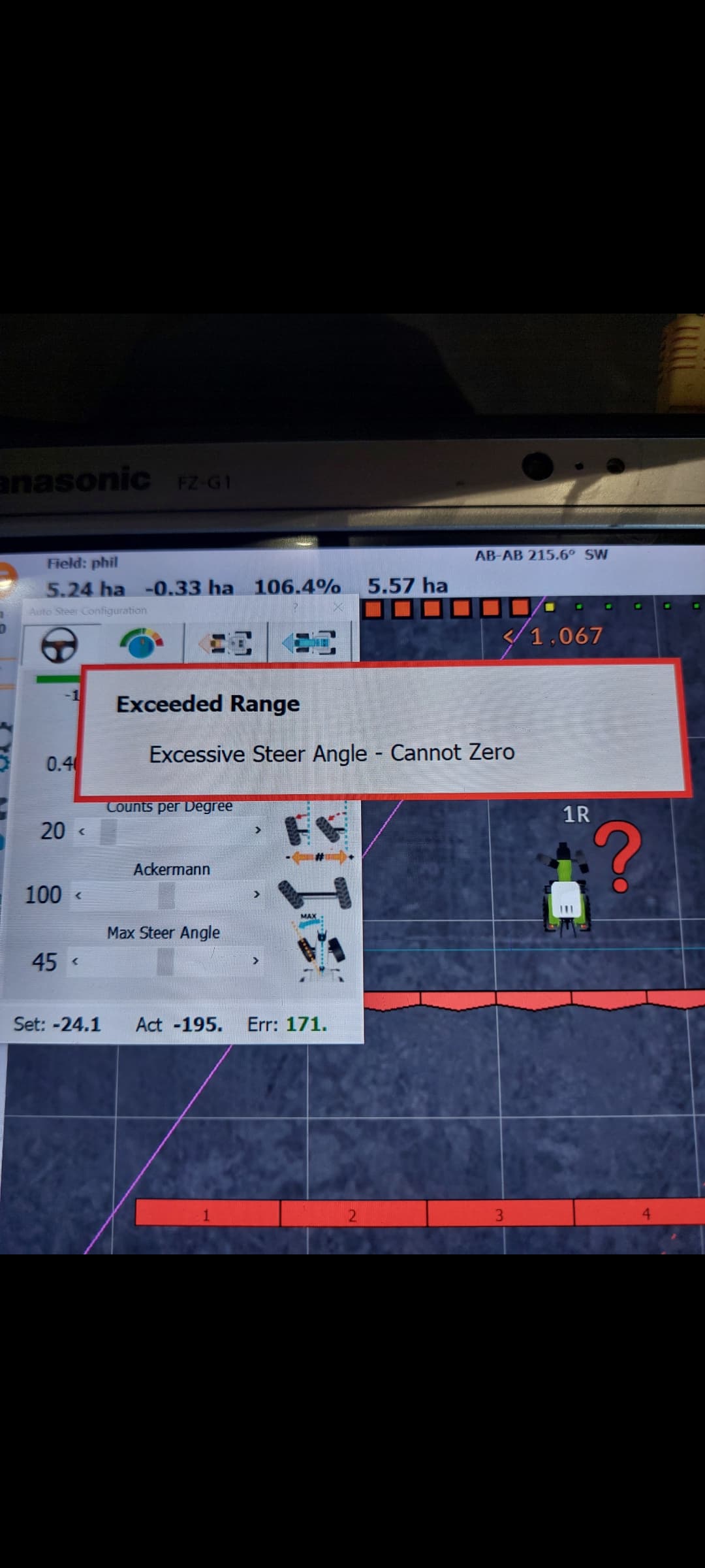
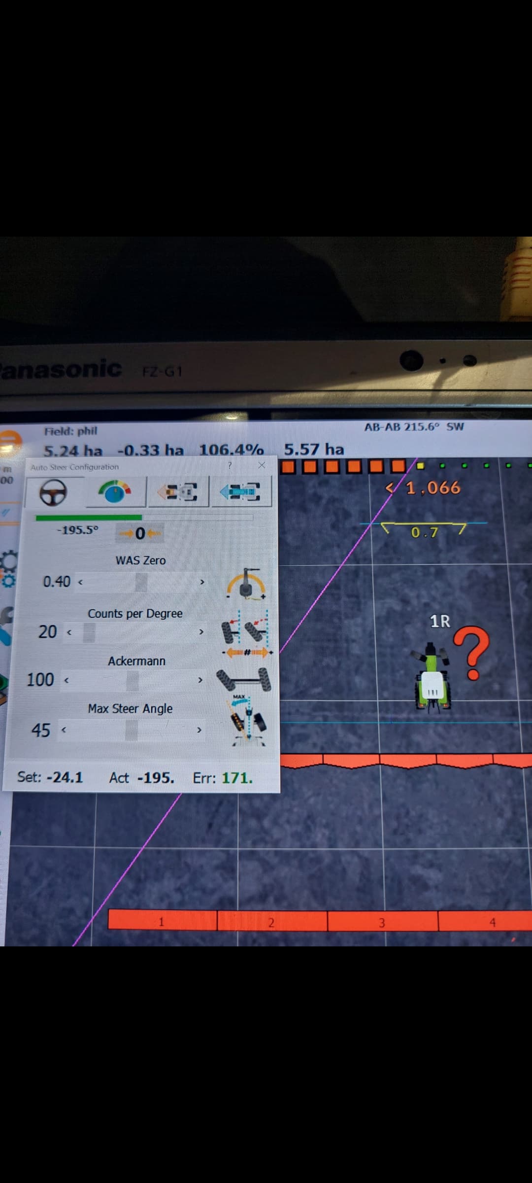
Tried setting the was again at 2.5v centre then pressed zero but still wont let me zero it.
Swapped it for a new sensor and plug still the same. Swapped the ads1115 (one i connected with header pins as the surface mounted one wasn’t instock at jlcpcb)

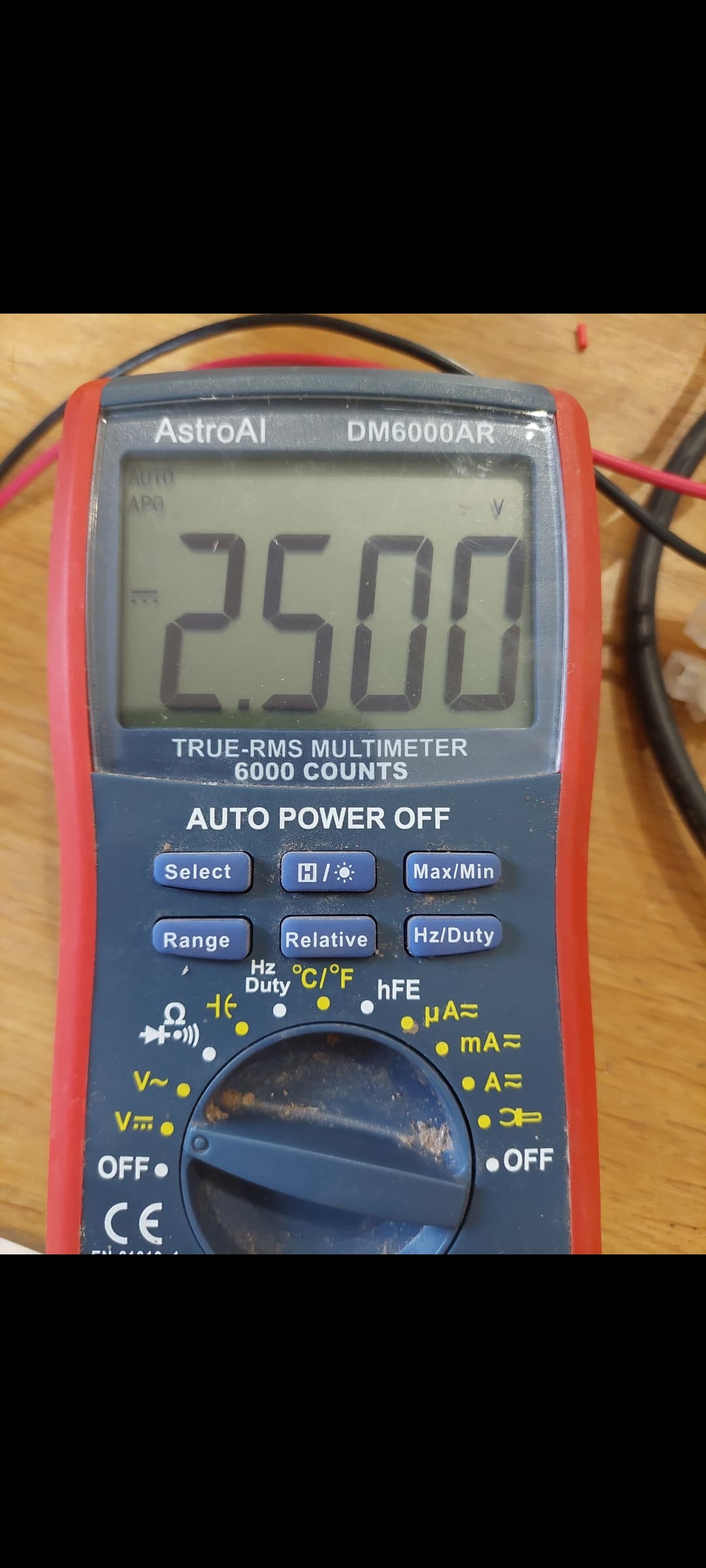
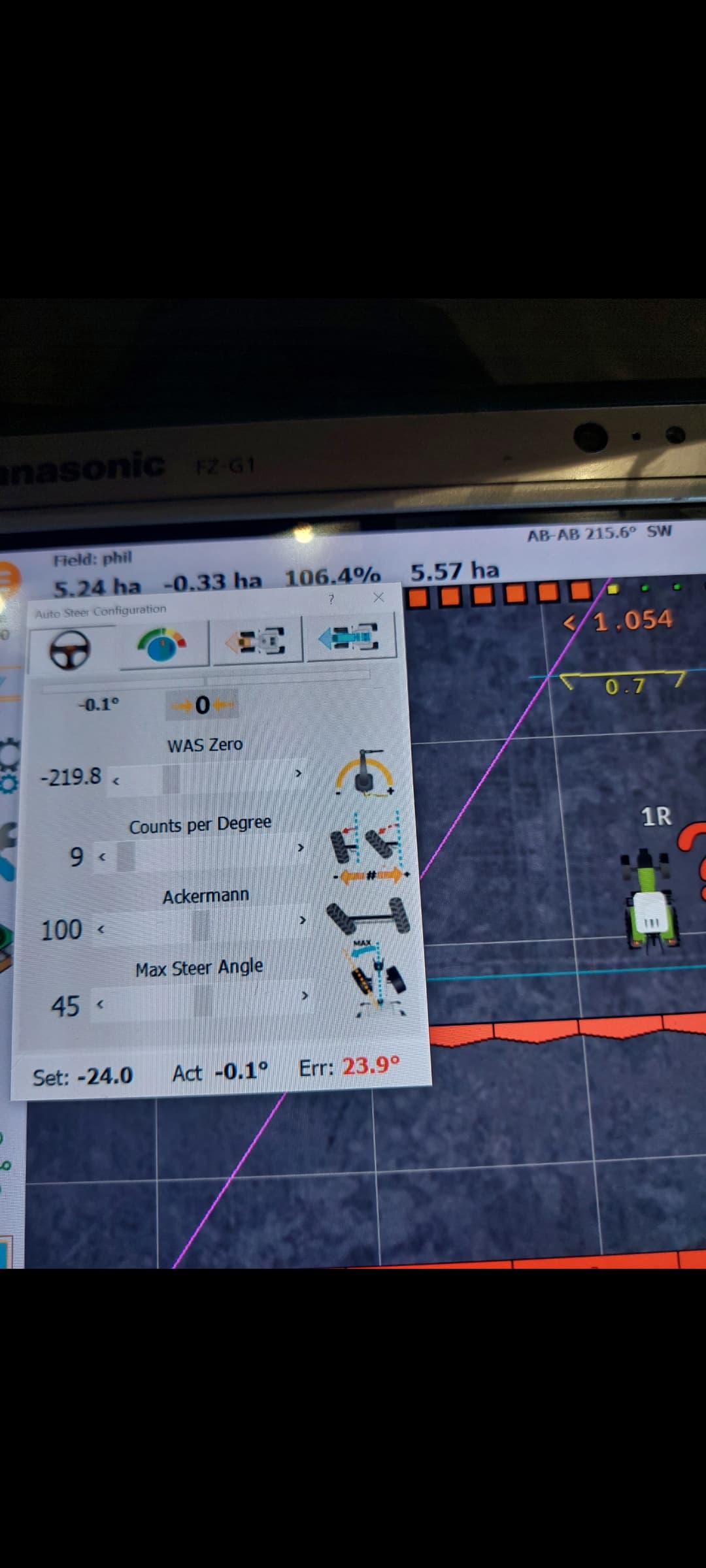
Try to reduce your counts per degree and try again. Try about 20 percent. The higher your counts are, the less room for error on the center voltage.
Let me know