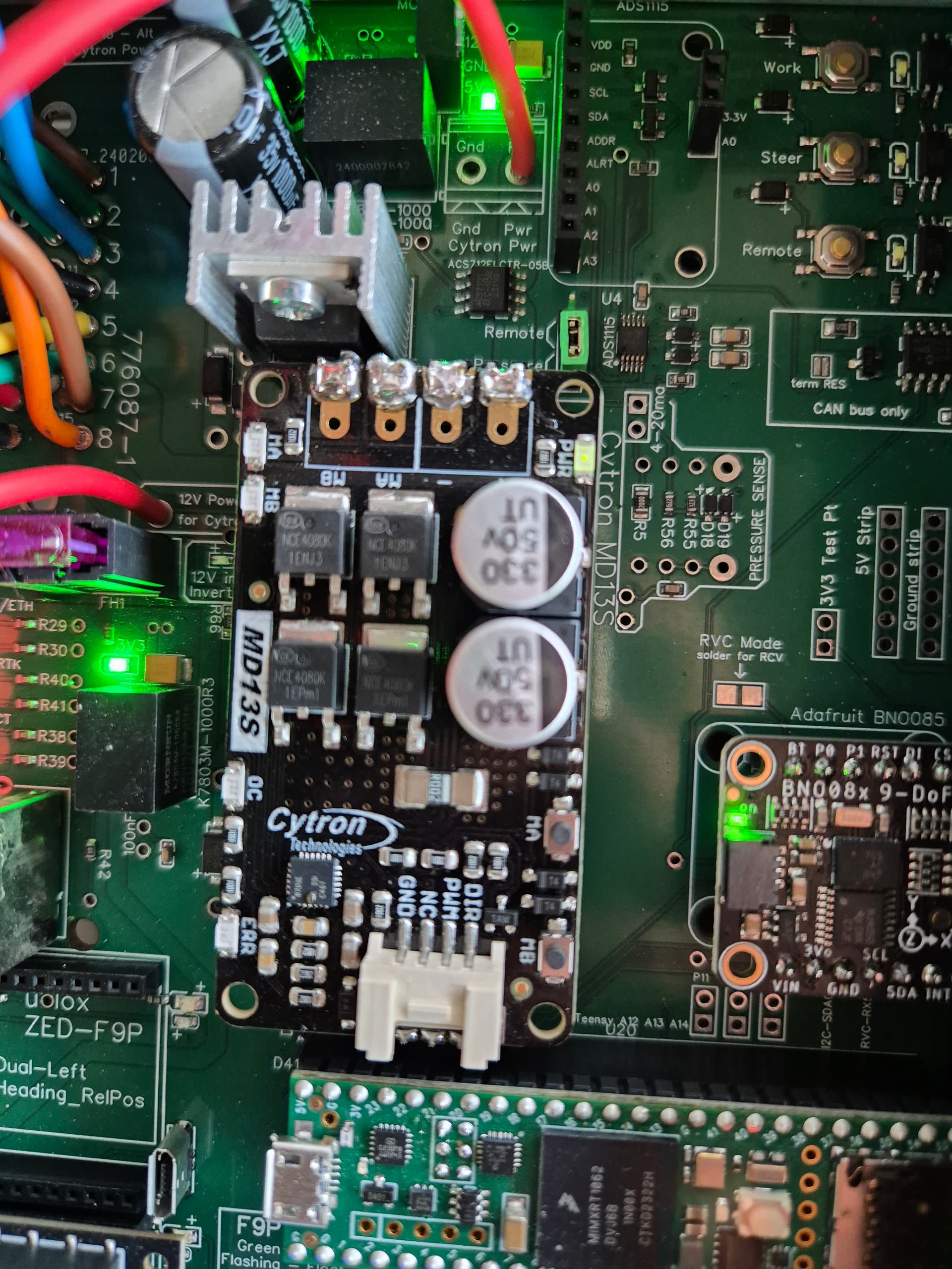
I have 12v on the + and - cytron terminals, the cytorn pwr led is on. if I press the ma or mb buttons I have the ma or mb LEDs lighting up and 12v on the ma or mb outputs. but I don’t have 12v on terminal 7.
so I don’t understand, but I tried it now and it works. The tractor follows the line in the yard. the start button also works.
All that remains is to make the adjustments.
I put the antenna above the cabin like the caseih gps.
Where did you put yours?
Thank you for your help
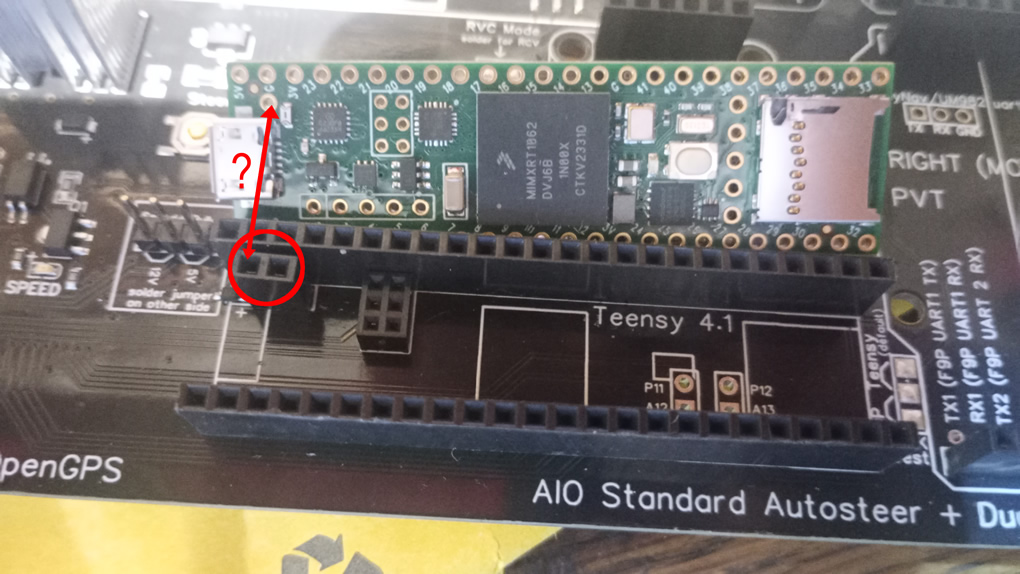
I’ve just got a 4.5 board. Obviously I still need to solder 2.54 & 2mm pins to teensy, but what about the extra pin I’ve circled? Does this need a pin too?
The extra pin is there so if you cut the jumper on the bottom of the teensy to isolate 5v power from usb, you can still flash the teensy without 12v power to the board.
Well, still a problem with my terminal 7 (lock). However it was working the other day.
Can you tell me if by pressing the red button in the photo, there will be 12 v on terminal 7?
I think it will, in fact I know it will cuz I played with it a lot. If autosteer activation mode is set to None than it will unlock. if its set to button or switch than u need to activate auto steer(by pushing the button or switch) and pwm(red icon on picture becomes green)
Board with F9P works like it should. Board with UM982 isn’t booting the teensy and the gps light doesn’t light up but the AS/ACT light does and that light doesn’t turn on on the F9P board. Swapped the known good teensy and same thing. Doesnt even light up the teensy lights.
Hello, I’m new here and I’ve been reading for quite a while and looking to start my building experience.
I’m in the process of ordering the PCB AIO V4.5 and I can’t find on JLCPCB one item such as the ‘‘MUPT8RE3’’ marked as ‘‘Teensy UMI Power’’ on the BOM.
How do you guys suggest me to proceed? thanks in advance and best regards
Guerins
Hello, I am a beginner and trying to assemble a system for myself. I ordered a 4.5 standard PCB from JLCPCB. After uploading the Gerber file, the PCB layers still show as 2. In the ordering instructions, I found that the layers should switch to 4, so I changed it manually. After placing the order, I received an email from a JLCPCB engineer stating that the file specifies 2 layers, and they asked if it should be corrected to 2 layers. I replied that it should be 4. However, I started to doubt if everything is correct. I took the files from the topic at the beginning.