All in One PCB

Ok ivr done some more testing. When the sensor is set at 2.1v
At the ads1115 in getting VDD and GND 5v
SCL 4.94V
SDA 4.94V
ADDR OV
ALRT 4.97V
A0 0.25V
A1 0V
A2 0V
A3 0V
Ive attached a picture of my ads1115 and whats underneath it


and when you move the sensor do you have differnt in A0?

I did try and i thought maybe it was changing but cant be 100% (couldn’t hold the probes and move sensor by myself)
Should i get a range of voltage at A0?
Do i definitely need this 1k resistor fitted with my style of ads1115

What I learned is that when not using the SMD ads1115 you need the resister. The 2 different ADS1115 boards work exactly the same, just that with the new one you have to wire the 4 pins in the board to the PCB. Without the resister, I believe you would have the same voltage at ampseal pin2 as you would have at one of the holes shown in this picture shown here. The other hole will probably match the ADS1115 A0. Using EasyEDA, you can put your cursor over the pins/holes and see the connections.

1 Like

Thankyou very much. Ive ordered some resistors so I’ll try that and report back

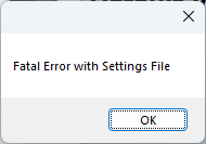
Having an issue getting vehicle settings files to load if anyone on this thread has experience with could you jump over to:
Vehicle settings file setup - Operations/Getting Started - AgOpenGPS
image

Is the remote/pressure jumper used at all with a steering motor or is that just for hydraulic steering systems?

Solution to my was not zeroing was adding the 1k resistor as mentioned above.
Tested sensor at 2.5 volts now it shows 2.5v on the ads1115 pin A0.
Connected the tablet and reset was, when moving the sensor the wheels on the screen move.
Thanks for the help and responses. (no idea how i find the 'solution tick ) button
What a brilliant community :+1:
On with the project and install

2 Likes

That’s great that your working. I was so happy when Patrick pointed out that problem for me.

1 Like

I was over the moon aswell.
Is there a way of testing the steer motor in simulator mode or do i just need to install it all in the tractor now? Got the was working, got the steer switch wired up and working, green light on the aio is going green for steering module. Can only get the motor to turn with pressing the buttons on the cytron

Use simulation.mode on bench. Make a button or switch connect pwm to motor and your ready to go.

Have got the switch set up which turns the little tractor green and red once pressed.
Got pin 5 and pin 6 going to steering motor and pin 8 to switch. Pin 7 nothing at present.
When pressing the MA MB buttons on cytron it powers the motor. In simulator mode it doesn’t turm the motor through, is it meant to, set an ab line and simulator follows that when i press the auto steer button but no activity from the motor

You’ve got the two jumpers to select Cytron output?

Yes. The left set (looking from the front) i have the 2 pins closest to the cytron connected and the right set the 2 right pins


Should also add that the green light on the aio pcb goes green when i press the autosteer switch

That looks good.

How about the three pins on the other end if the Cytron, there all good?

Ive edge soldierd the 3 pins in the end. Header pins were already in place. The PWM2 hole is empty though

The MA and MB buttons fire up the motor when pressed

Where are those wires going from left and right jumpers?

Yeah. Temporary jumper. Haven’t got the correct jumpers so rigged these up for now

Should the steer motor operate in simulator mode

Yes. If you have free wheel mod on Cytron, you need pwm2 connected but if MA MB buttons make motor turn then it should work in simulator. Also make sure to send steer settings to steering module