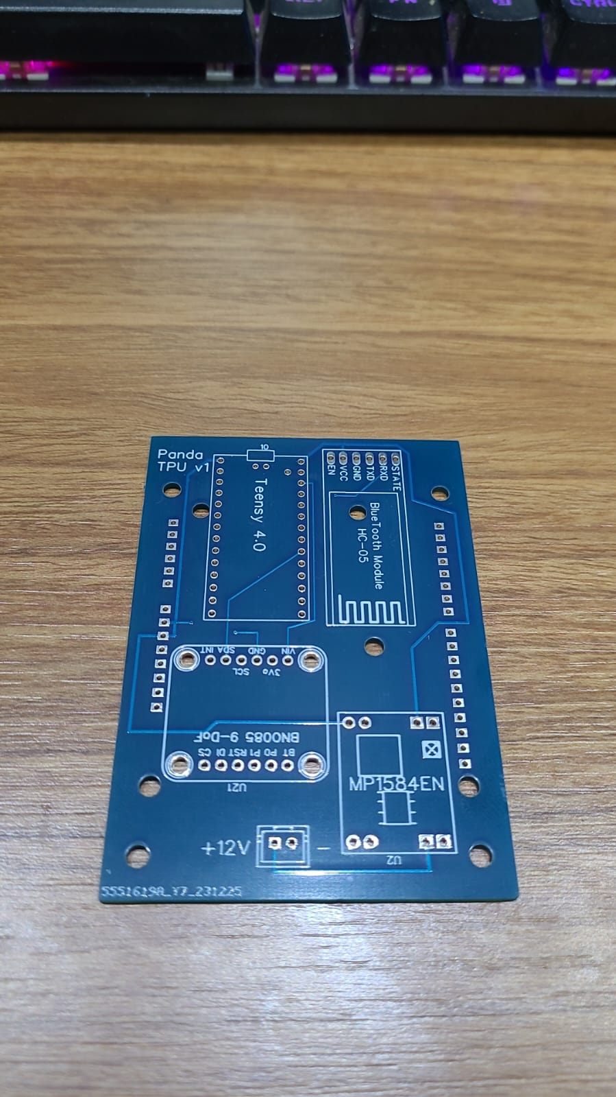
Update of the TPU as Panda TPU, as you guess by the name, with the aim to get the Panda synchronised data between position and IMU. it’s also few more compact.
1 Like
Hello BLO08, I’m sorry for the inconvenience, but I have a problem connecting to PANDATPU and I’m new to programming.
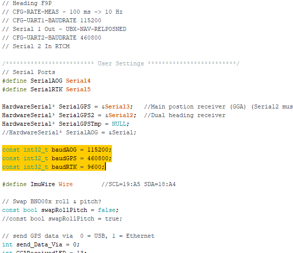
First I printed the pcb and assembled the components, I installed the PANDA firmware on the teensy, I configured the teensy with the .ino file and hc 05 as shown here. Ports prt F9p 5HZ 460800.
In AGIO I connect and the panda tpu keeps flashing green and red without working, I don’t know what I went wrong


I disagree, the discourse is made for this!
When you said you printed the PCB you mean ordered (I’m not sure you use PCB or wire version)?
When you start the TPU after ±30 seconds the teensy red (if I remember well) LED should blink indicating the teensy start to sent “PANDA sentences”. Does it?
Try to set your F9P rate to 10hz to check if someting change.
You can also change serialAOG value to “Serial” which is the USB port of teensy and try to connect by USB cable first, then if the connection is correct it would mean the problem is between the serial4 port of the teensy and HC-05.
I’m maybe wrong but it in agio it blink green/red I’m thinking about HC-05 configuration or bluetooth link problem, I would recommand you to first try to use another computer with bluetooth because it could be the bluetooth driver also.
Glad to see that the Panda TPU will be useful for someone, tell what you’ll find with these advices!
Yes, I ordered the PCB using the PCB version.
Exactly at the agio it flashes green/red.
I set the F9P rate to 10 Hz and nothing changes.
I think the error is teensy, is the firmware I updated correct? Look at the photo.
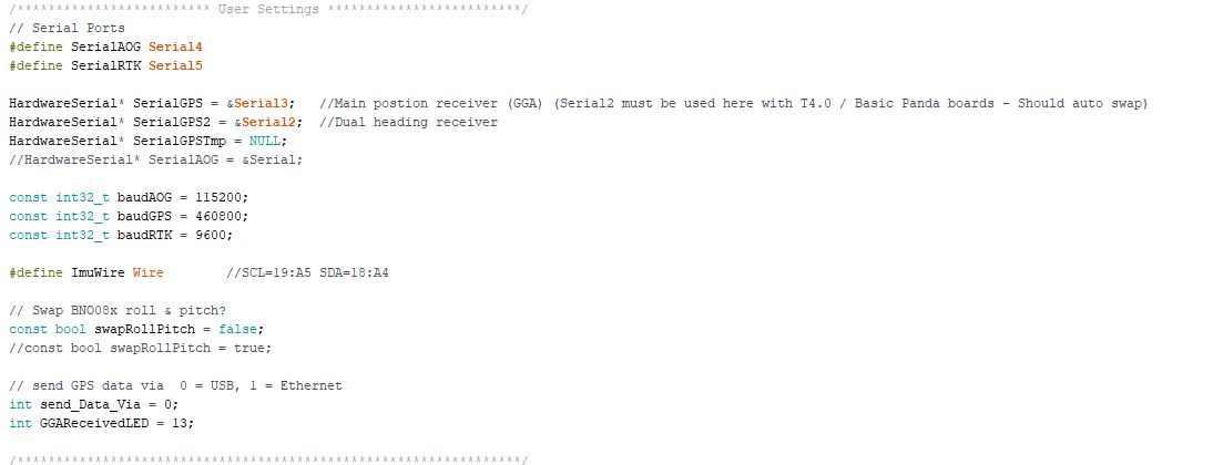
I updated the PANDA firmware and then on the Arduino ide I saved the file (Teensy4-0_v56_PandaTPU.ino)
The HC 05 settings are like this: -AT+ROLE=1 -AT+CLASS=0 -AT+CMODE=0 AT+UART=115200,0,0
Maybe the problem is because I didn’t mount bno085.

Exactly at the agio it flashes green/red
Meaning to me that the data received is incorrect. Possibly because The data itself is incorrect or because it’s inccorectly emitted.
I set the F9P rate to 10 Hz and nothing changes.
And USB test?
I think the error is teensy, is the firmware I updated correct? Look at the photo.
I’m unsure of what software you are using, I basically use arduino IDE with teensy loader.
Then when I see PANDA for PCB v2 I think this is for the usual all in one PCB that work only with teensy 4.1 and not 4.0, so not for the panda TPU!
Teensy4-0_v56_PandaTPU.ino
This would look more correct!
Maybe the problem is because I didn’t mount bno085
I must confess that I don’t totally remember but I believe yes, I simplified the code removing ADS feature (that forbidded to compile) and it’s very possible that I get rid of anything except BNO085 (some issue with my cmps14), I’ll check maybe this evening if I have time.
If you put the serialAOG on USB like I told, with the serial monitor of the IDE you should see at teensy startup if the teensy connect sucessfully to the IMU.
Hi!
I’m considering building a transferable gps unit to use with AOG but have a question to you guys that are using it already. How stable is the signal? Do you ever loose the connection to the HC-05 during operation so that you have to reconnect to it? When you start the system up does it always connect quickly? Do you sometimes experience problem with the bluetooth connection overall?
Hi,
I never experienced signal problem with HC-05 module, not with it, but by experience with the bluetooth of an ESP32 board, it still connect at 50m and probably more was possible.
I won’t say it can’t happen but I never lose signal at work, the main drawback of the HC-05 is it need enough power to work correclty, it’s supposed to be powered by 3.3v but some HC-05 are 5V tolerant and it ensure enough power.
One exception is when you start the motor of the tractor, voltage drop and you’ll often have to restart the TPU. This could probably be solved with a capacitor but anyway it’s not a real problem on my opinion.
The bluetooth connection in my mind is done instantaneously, or maybe it’s few seconds but very fast.
The main risk of problem is in fact the connections, this is why I solder everything, of course you can’t remove easily then but I don’t plan this and it’s safe.
Okay thanks!
Will definitely try it out! I totaly agree the more soldered the better, maybe it is harder to remove but you save those hours trying to find a loose connection…
Hi, I liked your project, but I have a problem
Error in PANDA TPU
AGIO recognizes the panda tpu and does not read the direction and speed
I am new to programming, the problem may be in the .ino file. If anyone can help, here is the .ino file and the HC-05 settings
-AT+ROLE=1 (MASTER)
-AT+CLASS=0
-AT+CMODE=0 -AT+UART=115200,0,0

Hi Pedro,
Glad to see my stuff useful for someone else.
If I understand well, you have green icon in AGIO and in AOG you have correct position but tractor is on the side and no speed.
Green icon mean communication is correct but if some data is missing (IMU disconnected for example) you won’t have position.
As you have position I guess everything on the hardware side is fine, if needed you can test it with USB connection on the teensy and serial monitor to watch the startup process and see if there is error.
However I don’t believe it’s your problem.
The fact you have a correct position in AOG mean the f9p provide GGA position messages and IMU the tilt that are mixed by the teensy to get real position (then transmitted to AOG).
In some version of AOG, the F9P need only GGA messages from f9p and calculate on it’s own speed and gps heading.
In some other you need GGA + VTG messages, VTG provide gps heading between 2 fix and speed.
Not totally sure to remember how it’s with panda but on my opinion your f9p is set to send GGA but not VTG and here is the problem. You should try to enable VTG message in the f9p configuration via U-center.
Don’t hesitate to write back here if you can’t solve this issue and sorry for the reply delay.
Good luck!
2 Likes
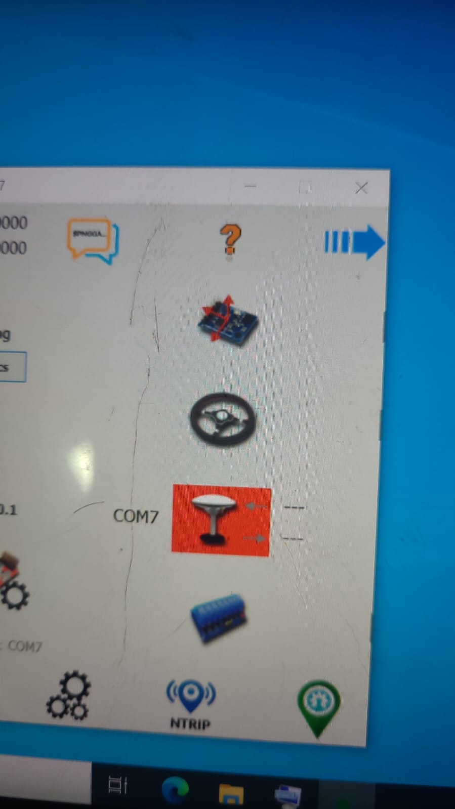
I’ve already tested it with a USB directly on the Teensy but I don’t have the position and speed.
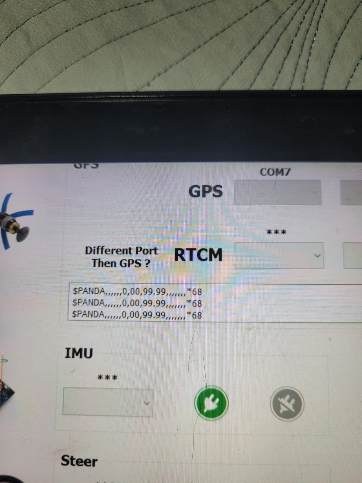
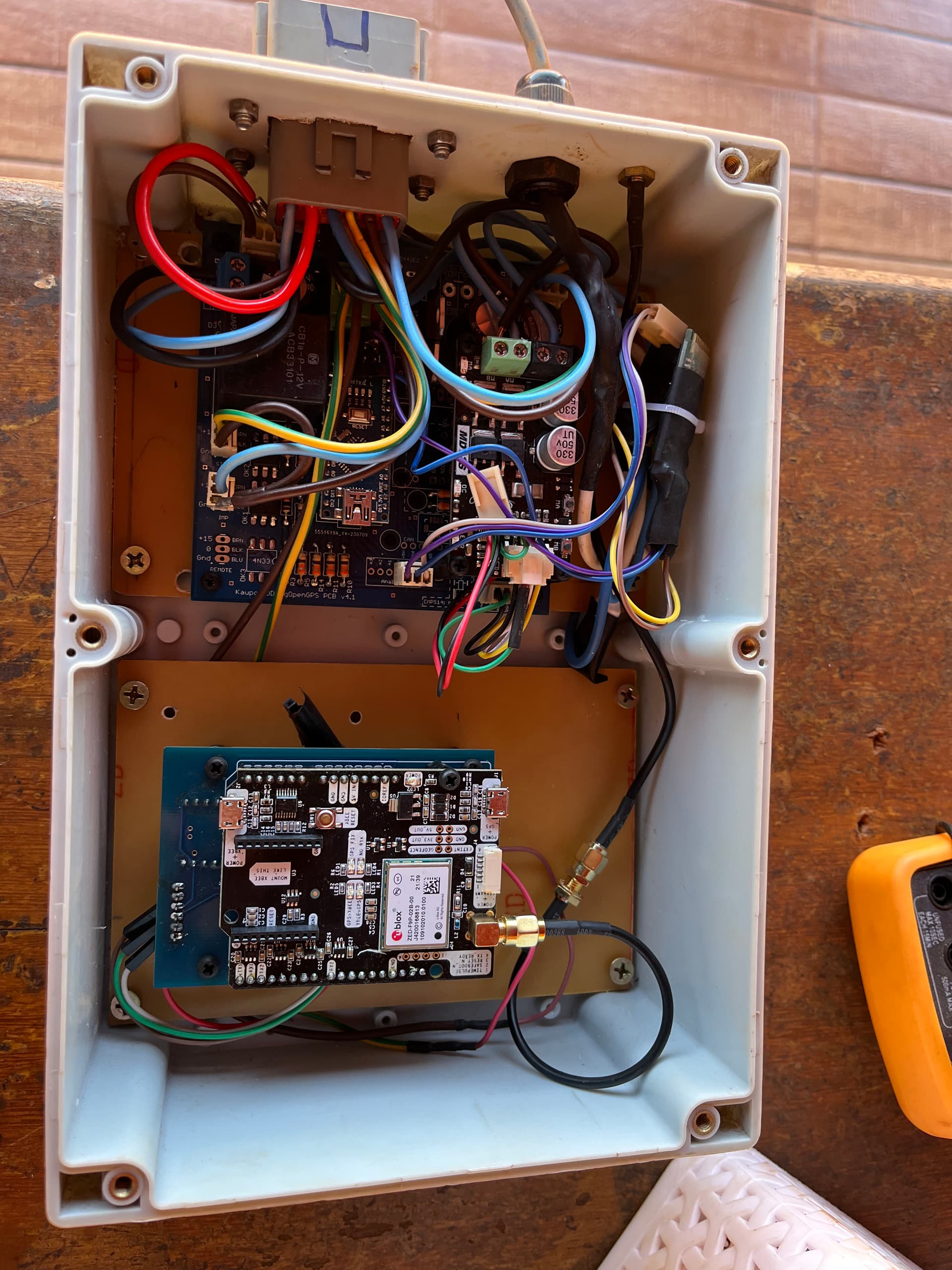
About f9p here is the configuration used.
GNSS = GPS + GAL + GLO
10HZ
Version 1.13
I have the position and inclination of the IMU working
I tried using version 1.32 of f9p and I have no speed or imu inclination
Thanks for the help ![]()
![]()

Or you can use AOGConfigOmatic to upload the the right F9P firmware and configuration.
2 Likes
On teensy USB you can never get position if I remember well, it’s only for debuging purpose, you can monitor how the teensy start and see if it detect the connection with IMU and F9P.
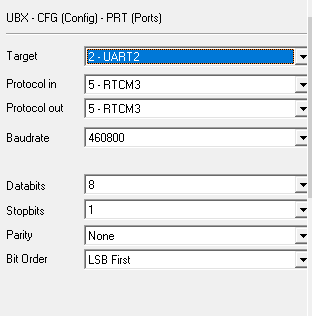
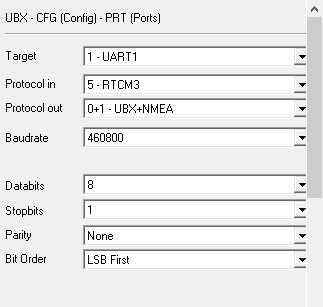
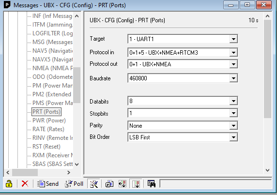
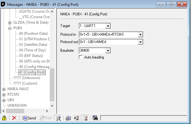
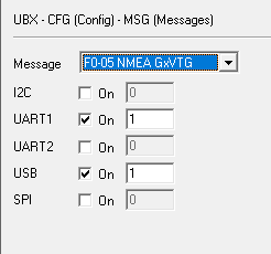
In U-center go to wiew>configuration view>MSG.
In the list you must find GGA (probably already ok) and VTG and be sure it’s enable on the UART you use for panda.
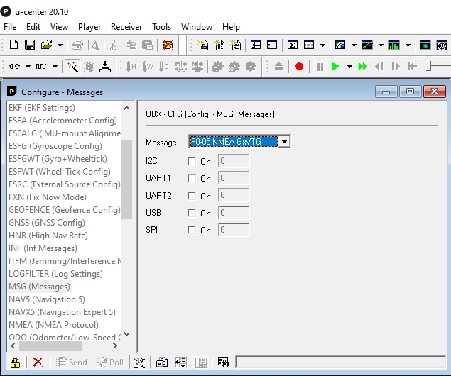
Photo without f9p connected, you must check the correct UART and save the configuration to make it permanent.
1 Like
yes VTG and GGA is enabled
I use the TPU panda pcb, UART 1
Maybe a firmware problem?
What is your IMU position when the box with your equipment is in place?
BNO085 must always be horizontal with the adafruit logo (or arrow I don’t remenber well) in forward position.