AOG Transferable hardware!

Hello,

I wanted to share here my project of transferable hardware.
Usually, there is one autosteer equipment per machine, each time you want to use autosteer on a new machine, or a machine that you use “rarely” like a combine for example, you need to make a complete new installation.

Of course you can tranfert to it from another already existing installation but there is some work to achieve it, inducing you won’t remove the hardware and will prefer install a new one to save time, this lead to one equipment per machine (usual logic) inducing cost for each machine…

I wanted to change this and make a versatile equipment that you can quickly install/remove to any machine, so it won’t be one equipment per machine but one equipment per driver.

To achieve it, some elements appeared:

  1. Cables take some time to install/remove, wireless is easier and save installation time.
  2. Separe totally positionning and autosteer allow to use positionning with any other device, including à simple computer without autosteer if you want to set your plot limit with the 4x4 of the farm, it make the system more versatile.
  3. Support of positionning and autosteer unit’s must be as simple as possible, fast to install/remove and convenient to use.

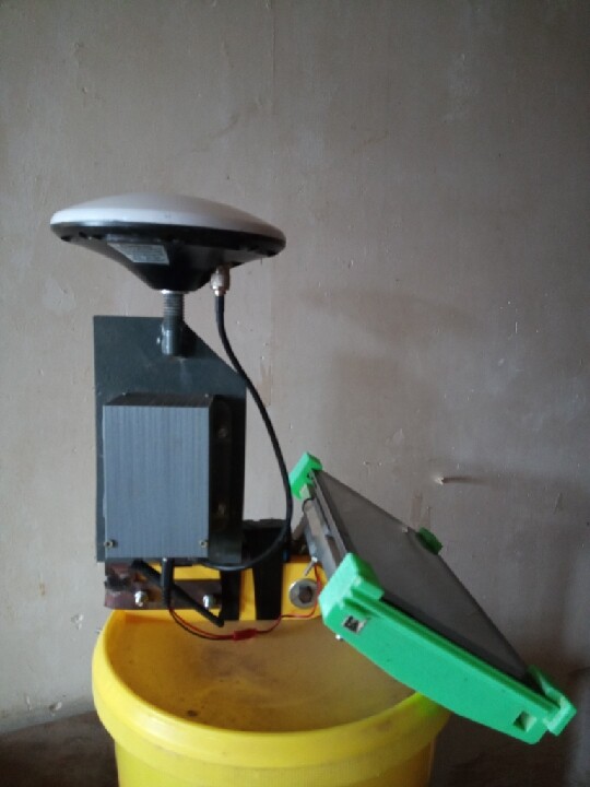
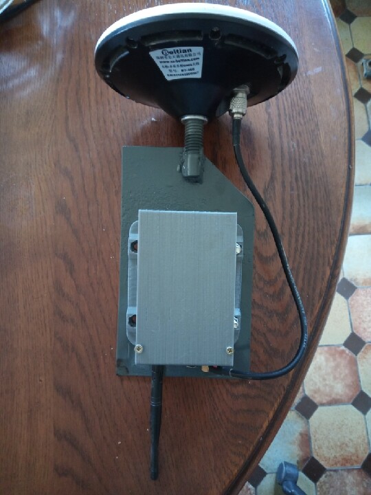
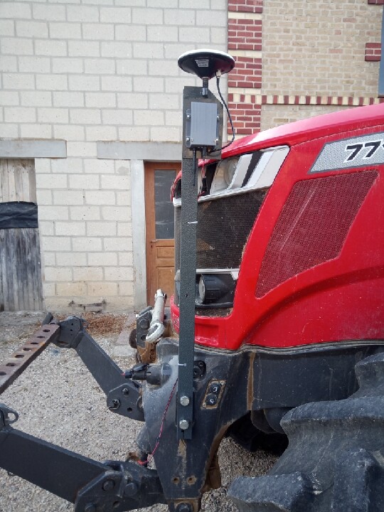
For those reason I designed first the TPU (transferable postionning unit), as a most compact as possible unit that should ensure signal reception (antenna), signal treatment (GNSS receiver), heading/roll correction (IMU) and their wireless transmission.

  • The antenna can be any correct antenna, I choosed beitian BT-160
  • Choosed receiver was C099-F9P because it directly have on board bluetooth/wifi capabilities, have 12v power supply
  • As IMU, CMPS14 gave me heading jump’s due to the use of magnetometers, BNO085 gave better results, a wemos D1R32 board was chosen for it’s bluetooth capabilities and the integrated 12v regulator.

However a step-dowm regulator was added prior to the receiver and IMU board because battery voltage can be 14.5V when engine is running!

The TPU take 1m30s to install/remove!
Only one cable (battery power).

Link to the full description and 3D files: https://www.thingiverse.com/thing:5182231


And of course, we also need a transferable autosteer unit (TASU)!
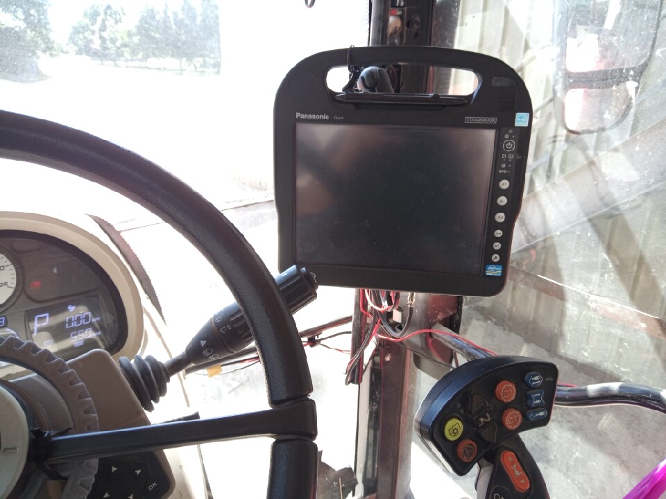
Usually there is the tablet computer and the pcb box but we want it fast to install remove so I decided to make of it only one stuff.

I choosed the Panasonic CF-H2 rugged tablet as basis because it’s cheap, the screen isn’t too big and it look really solid. Anymore the rubber handle, once removed offer super support!

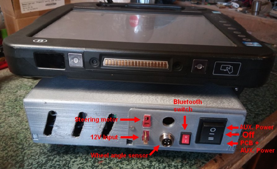
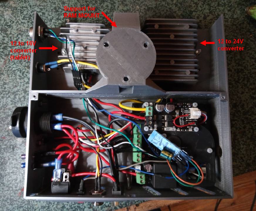
So the TASU is made from a tablet and PCB/voltage regalator’s box that also have the role of support for the entire system. As interface between TASU and tractor I used a RAM support which is few expensive but really convenient to use. Honestly it came with the isobus screen of the tractor that we don’t use because we don’t have the corresponding tool (it was +1€ when we bought the tractor).

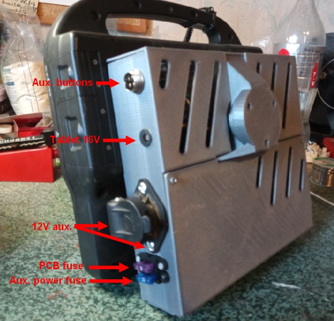
The support-box include place for a kaupoi PCB and cytron motor driver, control pannel with connector’s and switch, place for 2 step up voltage regulator, 12-24V for steering motor, 12-16V for the tablet power supply.

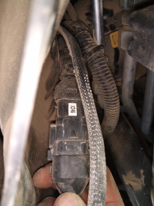
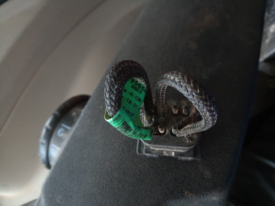
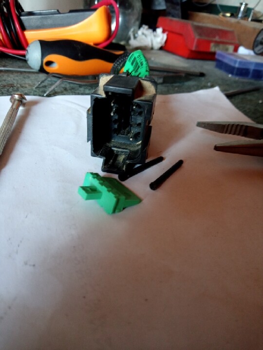
The side include auxiliary power ports, one 3 pin that replace the one took to supply the TASU that allow to use, for exemple, the computer of your fertilizer spreader or sprayer or any other, a round DC 12v connector for example if you want to supply a 4G modem to get internet and a 16v plug to supply the tablet.

Just take your TASU, srew the RAM support on the dedicated suport tube in the tractor and plug the 3 cables:

  • 12V battery
  • steering motor
  • wheel angle sensor

It’s ready to use in a couple of minutes!
Link to the full description and 3D files: https://www.thingiverse.com/thing:5376265


As you guess, all this don’t make the system totally transferable because the WAS and steering motor must stay on each machine, however, the main part of the hardware is simply and quickly TRANFERABLE!

Next step is to make a panda wireless positionning unit (if it’s possible, I didn’t seriously tought about it yet).

I hope my design can be useful for some other people or even can gave idea’s for some other designer.

Hooo… I nearly forgot… Thanks Brian!

8 Likes

your tractor seems to be ready, did you already have the WAS installed?, if so, you can operate it by can bus, you do not need the motor, and it uses all the original parts of the tractor.

1 Like

Thank you for sharing your project.

Have you had any field time with your setup? How is the reliability of the wireless link?

Have you seen the quick-tach motor holder project? It uses a dovetail and pin to mount the steering motor and makes the steer motor easy/fast to swap between tractors. It would go nicely with your setup. Universal Fit Gear System, with Quick Tach Motor Holder

Things that I really like are the fuse holders, laptop voltage converter, and the idea to mount the PCB to the tablet. These are ideas that can be used by anyone.

I use the integrated WAS, signal taken on connector X246 connector cap near the orbitrol. It need to add 2 pin to this connector cap in order to get signal and grounf (see photos).


This tractor don’t have GPS pre-equipment (electro-hydraulic orbitrol) so it need a steering motor.
Anyway this system is made to be versatile so it’s needed to adapt to any machine, which mean, be able to handle steering motor.
I have another MF with the steering electro hydraulic valves on it, via can-bus, PCB will be useless, but still needed for all others machine of the farm…

2 Likes

Yes I did, mainly with the previous version of the TPU made with CMPS14, however the tractor engine proximity made magnetic interferences and on that IMU you can’t disable use of the magnetometers. I put the CMPS14 in the cab temporarily in order to check if it’s really the reason and it was super at field.
So I switched to the BNO085, aog automatically set that IMU in it “game vector mode” that ignore magnetometers and now all seem fine.

I have 0 problem with the IMU on bluetooth, you can find the sketch that fit D1R32 in the support files of V5.6.2 (was done by me, small modification on basis of the USB sketch).

The GNSS receiver (C099-F9P) was more sensible, in bluetooth it seemed better for me to don’t exceed 5hz (configuration files is enclosed on thingiverse), I don’t know why because in U-center, even at 9600bps you can easily get the 10 GGA messages by seconds on bluetooth but AGIO reject too much NMEA packets (number up to the AGIO icon in AOG). On 5hz it’s ok and reliable for some full day at stubble breaking.
Maybe it’s due to bluetooth driver…

I saw the quick attach system, it’s pretty nice however it seemed to me difficult to adapt.
I modified a file from cerea to get a “punch emergency switch” that seem really fine in use (see video https://youtu.be/jQPdM2videM.)

1 Like

Did you attach the holder to the only plastic housing?

Yes it’s designed for RAM mount type C or D attached with 3 M6 bolt if I remember well, technically D size is more appropriate but I use C type and it’s ok.

The design is made to be as solid as possible and since now, even when it stayed closed windows by 35°C I noticed no problem about it. The choice of material is important, probably PETG would even be better than the high temperature PLA that I used.

I don’t know where you live, but when it was 35 degrees outside in my country, the inside of my vehicle was 55 degrees, and the PLA part was warped, as you said, choosing PETG or ABS (I know it’s hard to print) would be good.

HT PLA is supposed to resist 80°c (100°c if preheated in oven).
However there is still risk on thin walls under constraint.

Prsentation video of TPU + TASU working together : https://youtu.be/ddUHB-aU0w4

1 Like

Thanks for sharing Bl08,
I have a mf 7718 dynavt, with no gps preinstallation, i find this opportunity to use the tractor WAS very interesting.

Are those pictures inside the cabine or right out near the firewall?

Also, i would love to use this approach in other machines (class ares 826, and harvester nh cx8060), how did you find out that that was the right point to read the WAS signal?

The X246 connector is located front of the cab near the orbitrol behind a rubber protection.
There is a cap pluged in with 2 jumper cables, you’ll have to add 2 pins inside the cap (was signal and GND).
I don’t know on others machines except NH T6/7.

Versatility example : TPU with tablet as a plot limiter hand tool.

Thanks BL08, I will try to find it.
On the other hand, I know how to take the buttons pressed on the driving joystic of my MF7718 through can-bus. However I could not identify that specific WAS message, perhaps I was looking into the other can-bus, I believe they have 2 can. Do you think that sensor is also in the can-bus info?

First, its probably possible to take the sensor angle on the can-bus IF you simulate a quicksteer or autosteer mode (inactive buttons on the cabin side) that probably require to reprogram the ECU’s, but the main interest of canbus is to steer the tractor without steering motor in cab and if the tractor isn’t autosteer-ready it’s impossible.

Second the WAS data on the canbus is relative to the WAS center point setted on the canbus, you can’t adjust it via AOG so you need the dealer tool (I have this problem on my 7720 AS-ready).

Third, the last interest of the canbus here is the joystick button, to me that’s a too small aim for the work it will ask on my opinion.

I have the classic system on my 7715 and my 7720 will use canbus because ASready, for me you are in the same conditions than my 7715 and classic system (not canbus) seem clearly the best option.

Thanks, glad to see that you have already check the canbus message.

Obviously I would do some adjustments in the ino in order to accomodate my need. I have done in the past :wink:

Do you remember the message id for that sensor?

On the right hand side of the seat, near the floor, where the can connections are, there are two canbus conections, for the two networks that the tractor has available in that area. Do you know if it is in the same can network than the joysticks or is in the more general can network?

I never know the message ID of the WAS, I only know the sketch I used for my CAN to USB interface only work when one of the cabin side button about valve’s (autosteer pre-arm or quicksteer) is enable, without it, you won’t be able to receive the WAS position message.

About the 2 CAN, I used X230 and one guy succeed to make work the joystick button, I didn’t tested yet but that prove the joystick button is on the same CAN network.

How do you find the CF-H2 tablet, is AgopenGPS nice and clear on the screen ?

It is the same as the fz g1 in size and brightness, only it is heavier and bulkier, it can be more difficult to support. I have one but I don’t use it for AOG, the ones I use are CF d1 because of its large screen size

I don’t know other’s but I’m very glad of the CF-H2, the resolution is 1024x768 which is the minimum for AOG. It induce that the buttons on scrren to switch on/off autosteer or to mark are very large and easy to press even when the tractor move hardly.
The 2 drawbacks for me it’s when you must perform some settings the window you open take large place over AOG sreen and the plastic handle which is few big and take some field of view uselessly for our purpose.

1 Like

For sure the fz-g1 is better, but price is different. Problem of the cf-h2, it’s more and more difficult to find.