Since This February @lolo85 get request to use section control with Hardi sprayer
The electronic was hard to hack because compact and i propose a challenge with him to do mecanical control
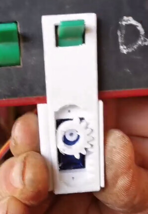
First sample test
After lot of sample and test final solution was adopted
so today AOGmatic is compatible with controler box for ::
@Daniel join the story and give Help to control Arduino Code
servo need to push
servo need to pull
servo need to be return ton midle position to be ready to next action or give opportunity to use mannually
The smart Code of @Daniel permit to manage well individually the servo
6 month after, evry thing is available
Final result in virtual 3D
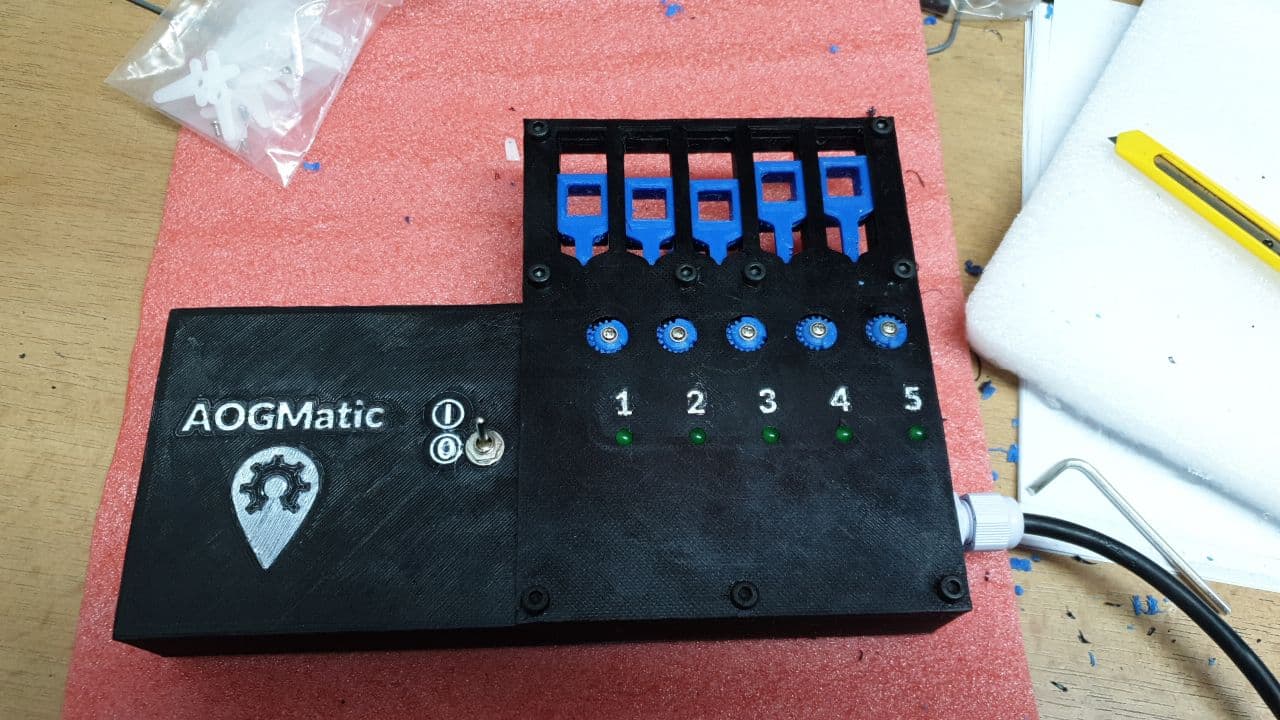
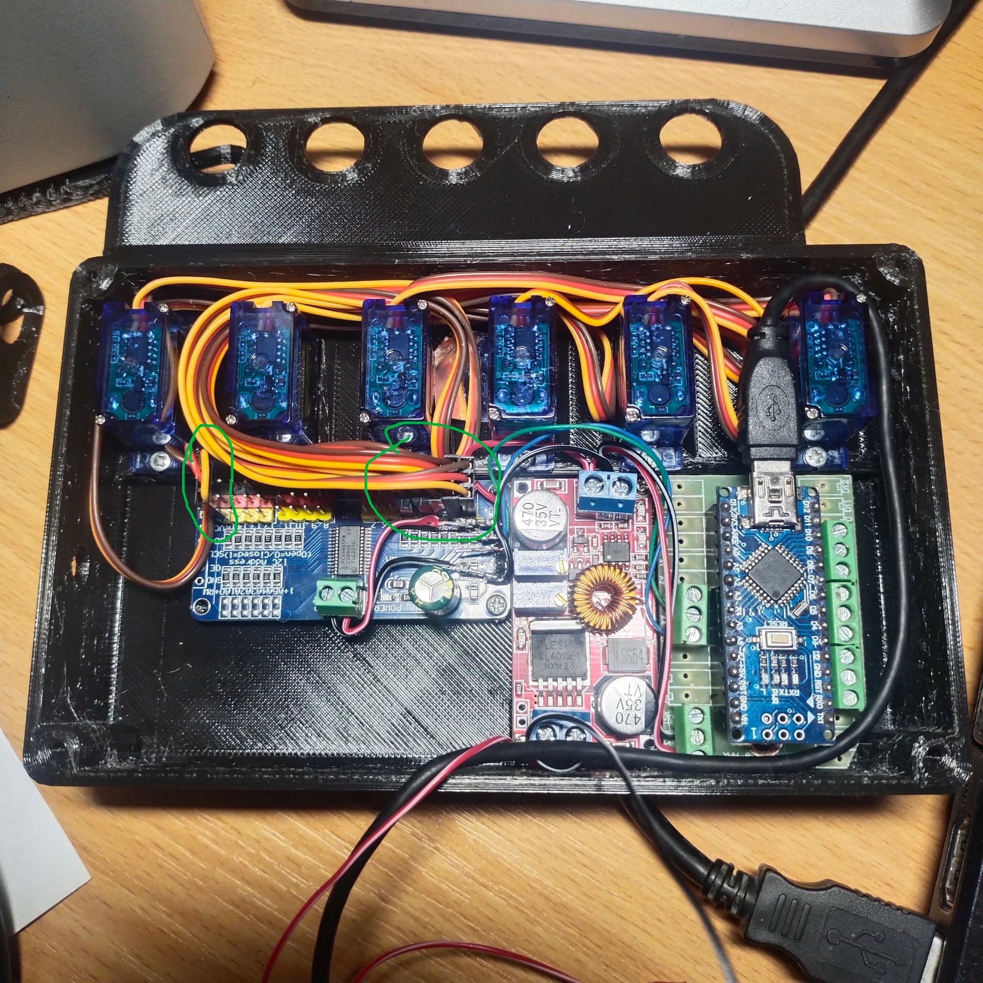
Final result in 3D printing
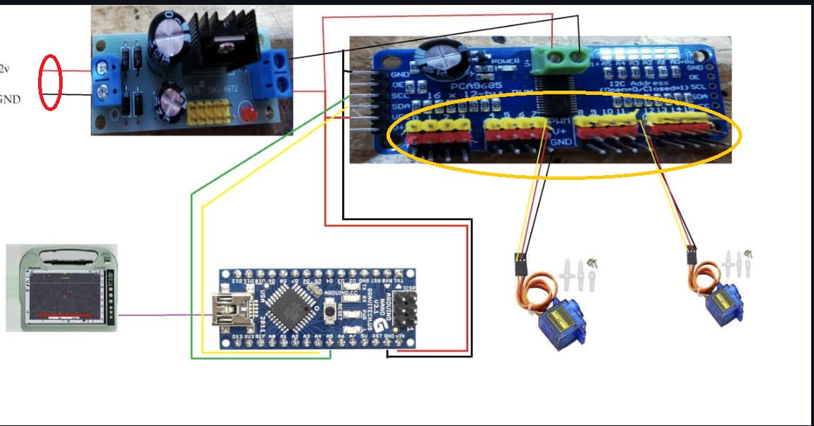
Final Code can be download here for USB or UDP
Final 3D printing can be dowload here
As test Bonus Pin A0 to the ground give a good demo , move check the screen,
13 Likes
Example of reality by using AOGmatic from Jean Marc in Bean field
3 Likes
Vili
19 November 2023 07:46
3
Version for Tecnoma with Axis Box
5 Likes
AOGmatic_USB.ino (18,4 КБ)cepega83@mail.ru
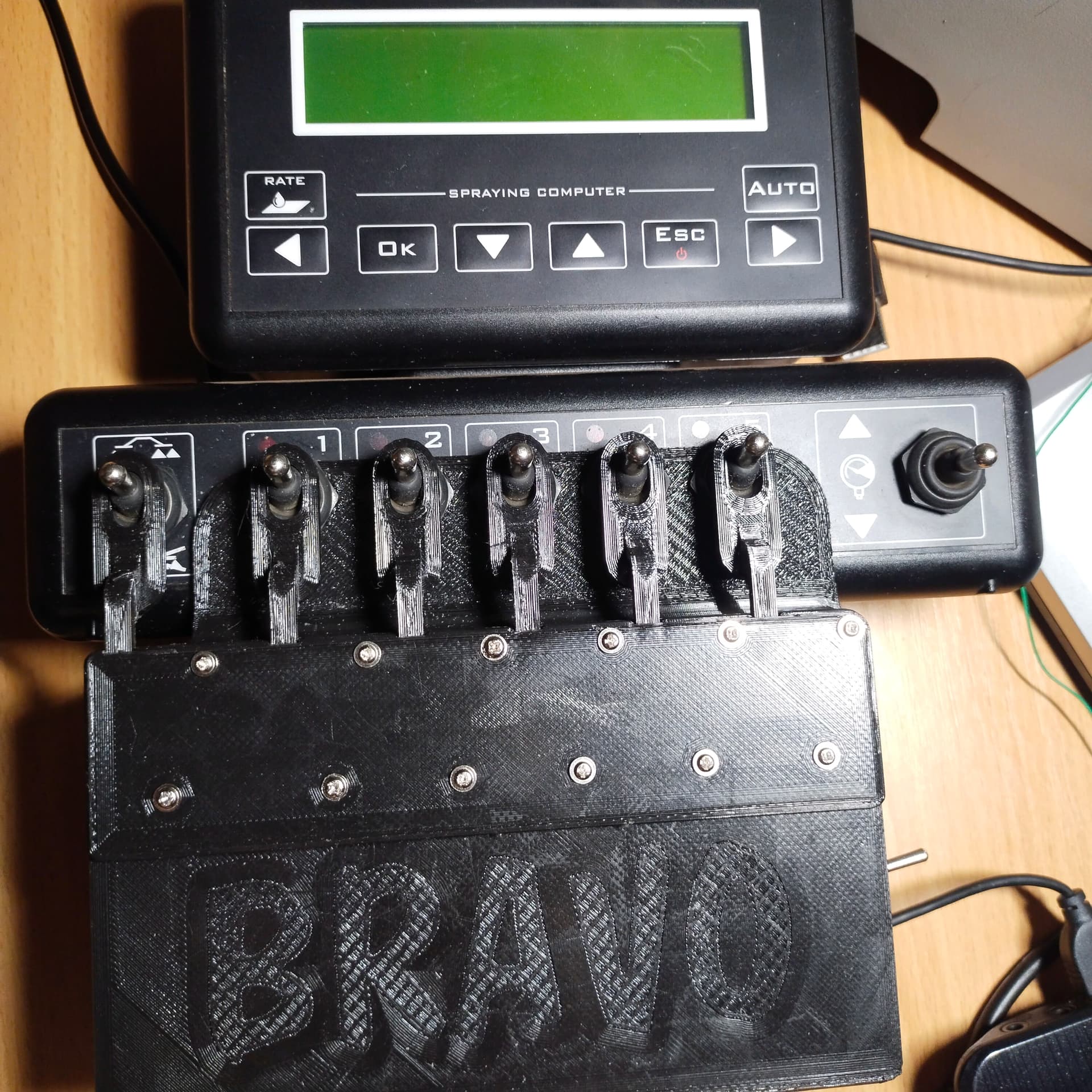
https://cults3d.com/en/3d-model/gadget/aogmatic-for-bravo-180s
Sections 1-5 are connected to pins 0-4. The main section is connected to the 15th outermost pin.
6 Likes
“Bravo” in french congratulation !
1 Like
do you guys sell a complete aogmatic set up for the hardi master ?
hello
add a message in forum to search sales man they are more and more businessman for that
if you want modification i can try to do it
It’s ok I managed to get someone to print the parts
In arduino Code
There is a dedicated line !
so if this line is active you can use switch to have a remote
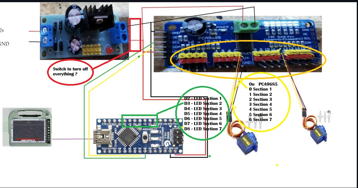
Nano pin allowed for this are describe :
For LED function
Pin of nano to
Connect Led+ resistor( 330 ohm) to the ground
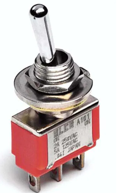
For switch remode fonction
Pin of nano to
Connect switch to the ground
thanks @Daniel
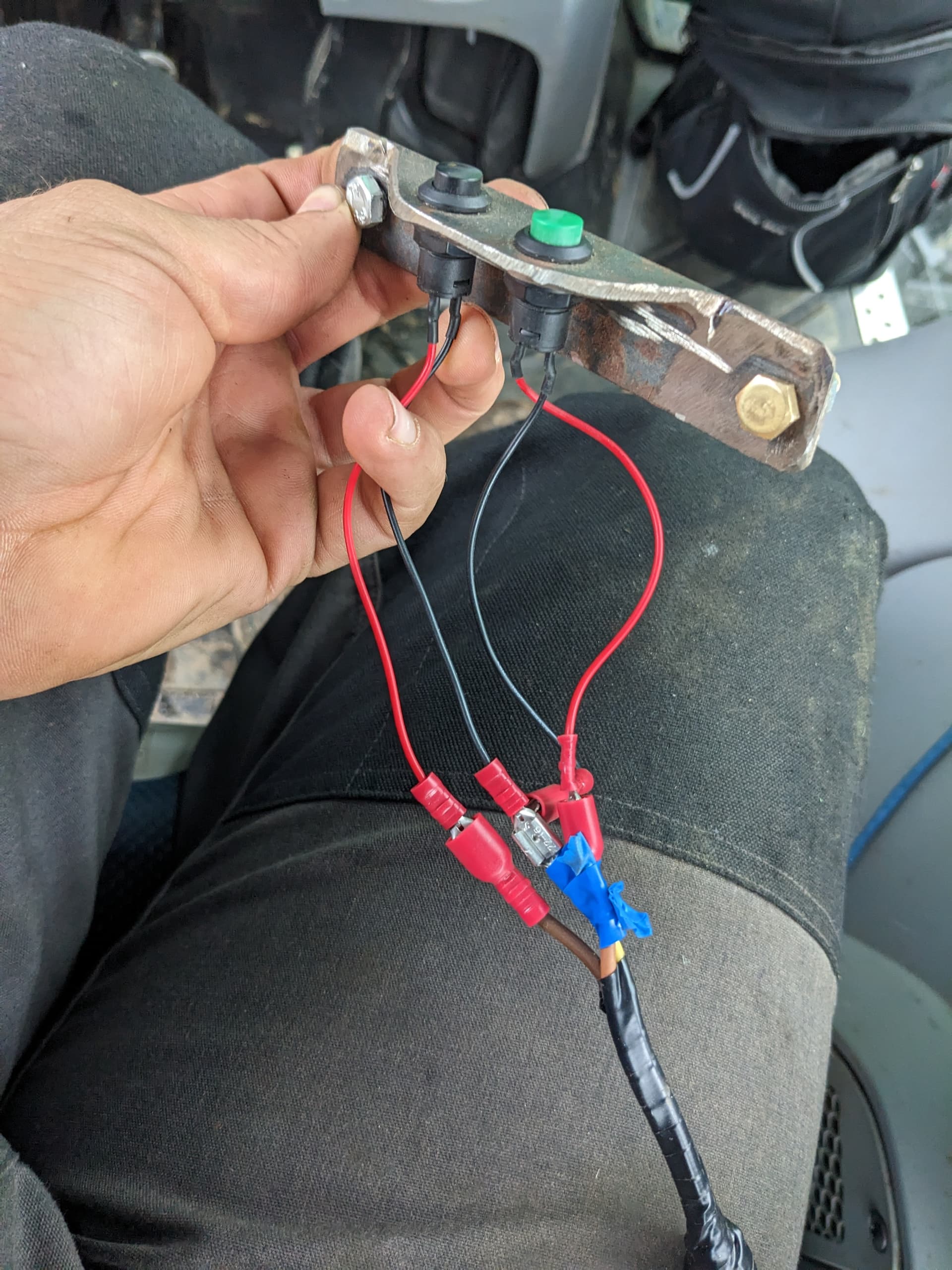
Hi Daniel I didn’t really get it I have a few bits already and ordered a few more could you just check if this is all ok?
#define ManuelSwitch 11 //Switch Mode Manuel On/Off >> to activate manual mode ( gree icon in AOG)
for auto/manual switch better to use ON OFF ON switch
bricbric:
ON OFF ON switch
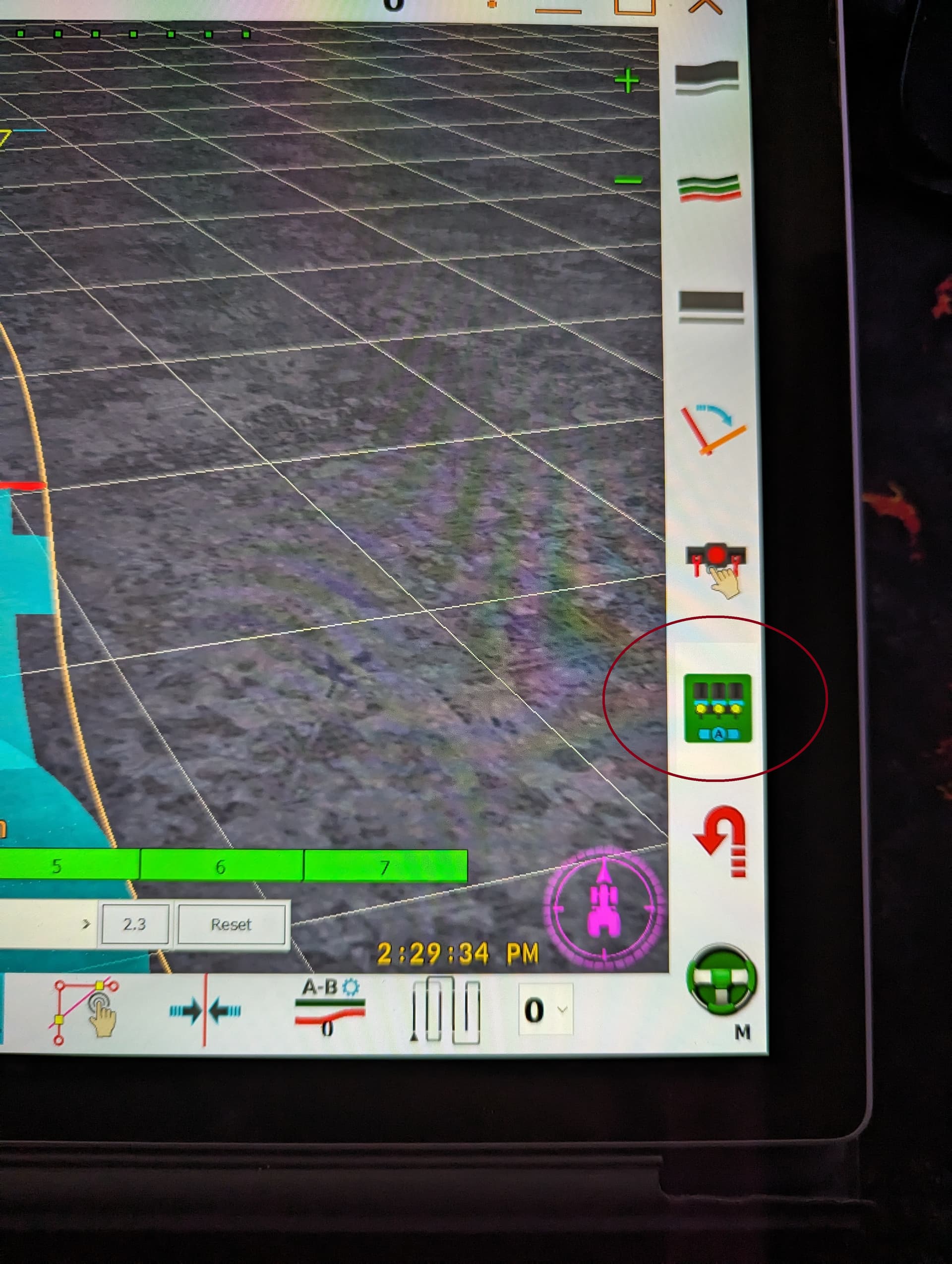
on may agopen gps i already have the auto secton button will i need another one ?
green is to engage the autosteer and black for auto section control
for this application tractor & sparayer
so while i use the sprayer i cant use the auto section on the main board of agopen gpe will have to use the one on the arduino nano ?
oh ok
1 Like

 Controle Section avec un Servo pour Hardi SprayII (Evrard EC2500) avec AgopenGps")
")