You changing wrong part, like torriem has written. And leave the 16mhz at 16mhz because that is what you have.
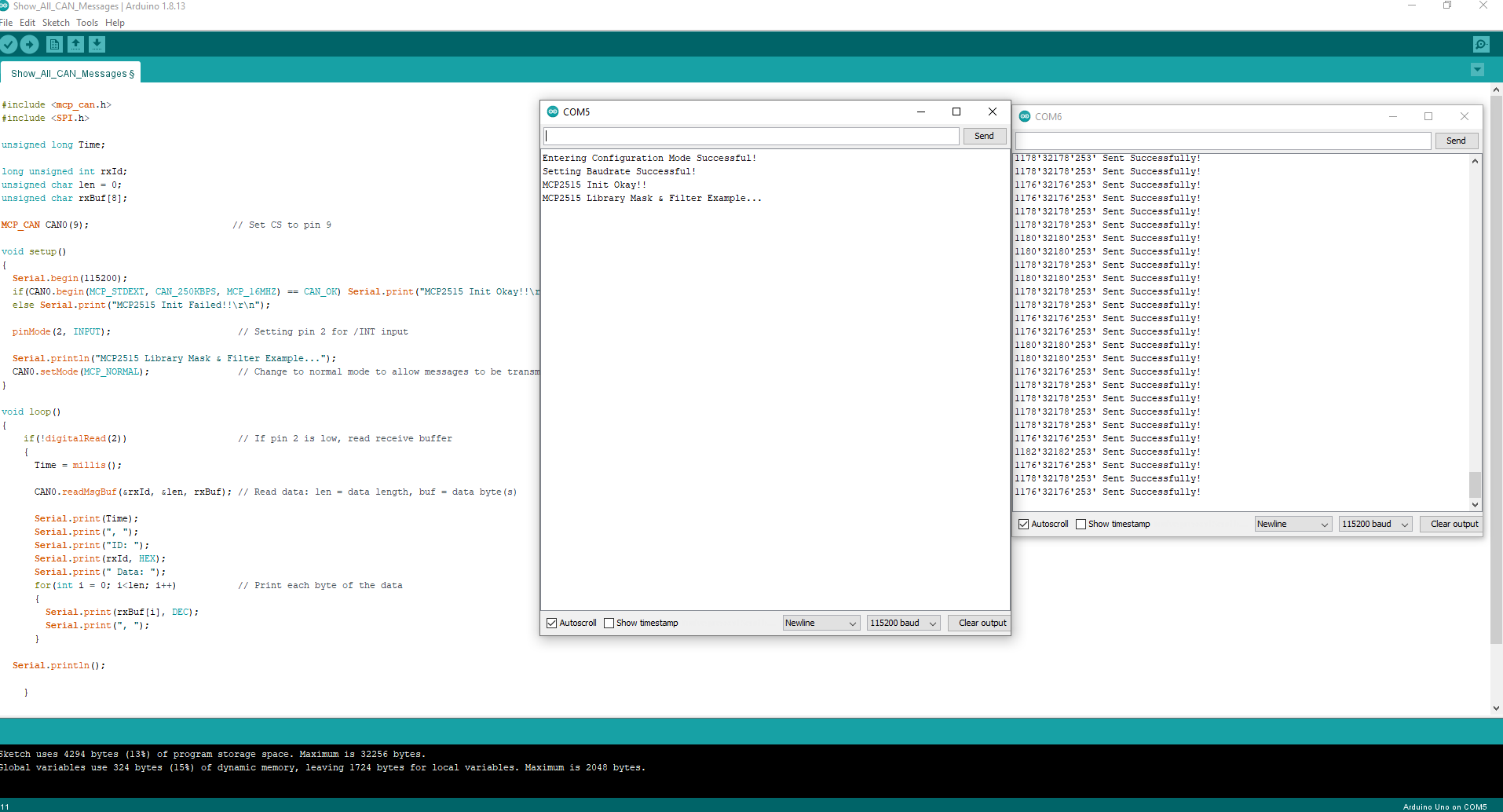
So i changed to pin 9 now correctly and it says that everything was successful. But nothing is scrolling.
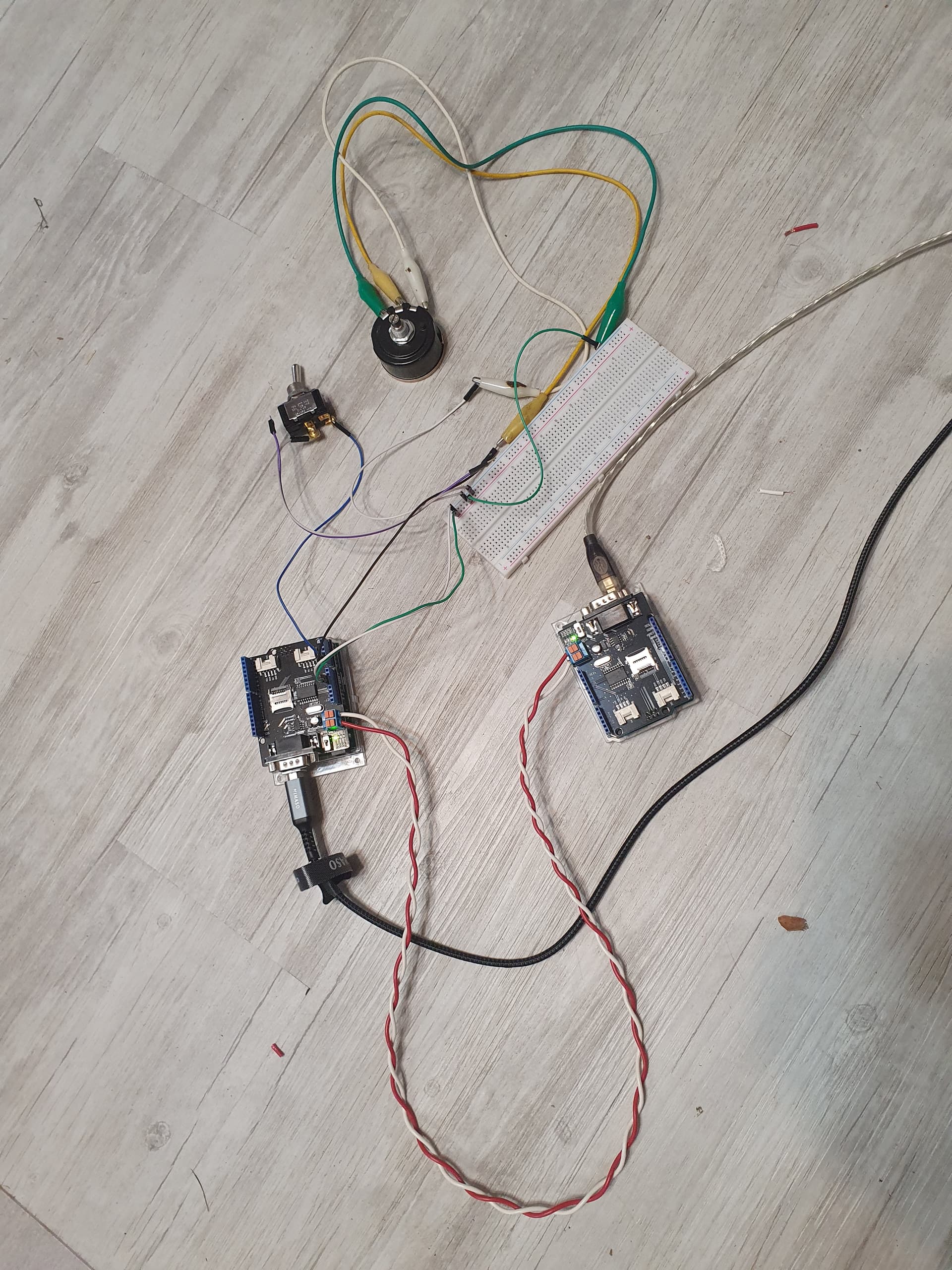
I have my other ardunio hooked up with a twisted together wires like the pictures.
IS this correct or am i still missing something.
The wires are:
CAN-H to CAN-H
CAN-L to CAN-L
And at the top of the sending Arduino, what did it say there? Have you also changed that program CS=9
Here is my arduino set up, canH to can H and canL to canL everything like it was pictured. (dont mind my messy wire setup)
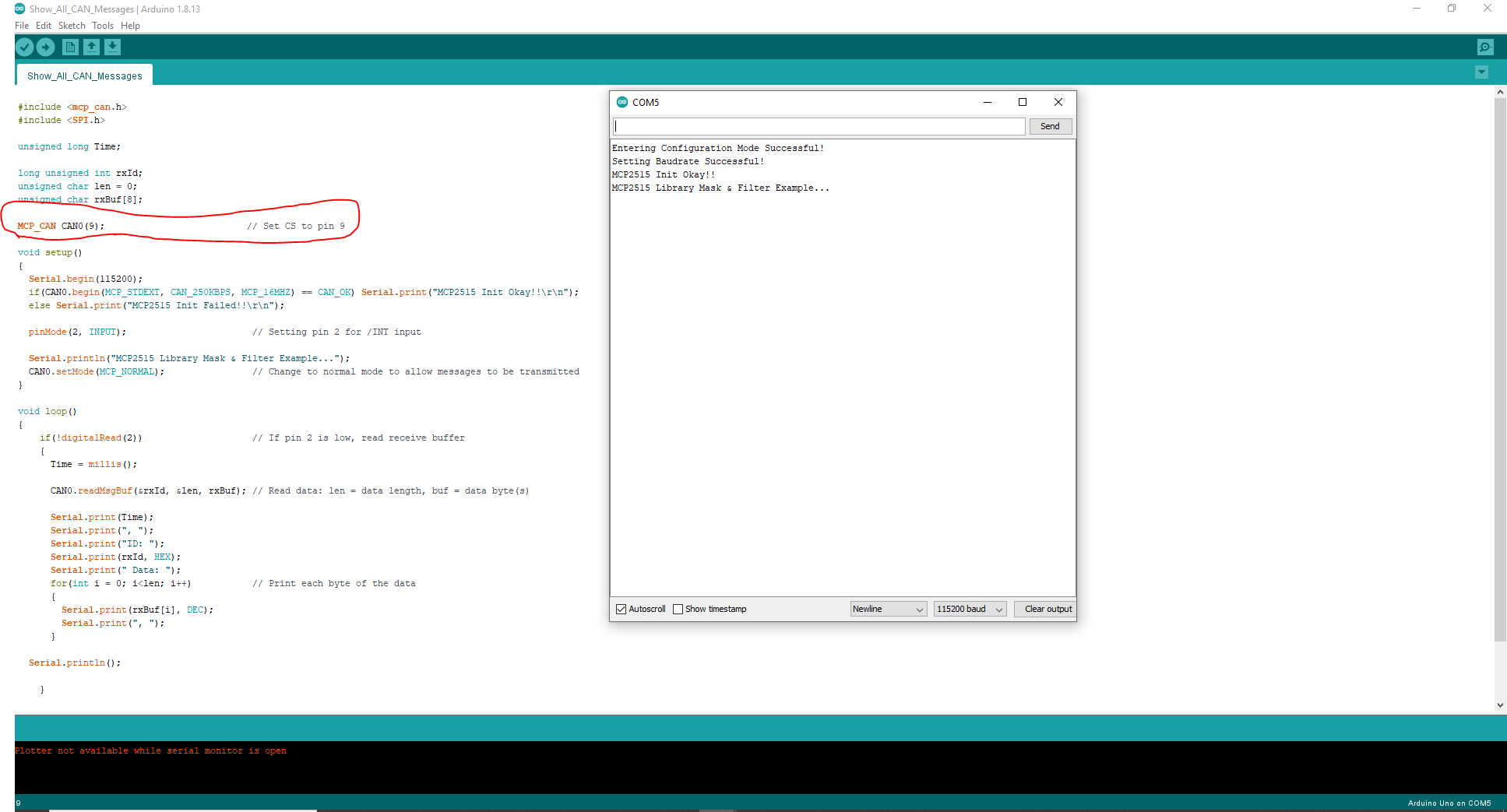
And this is my arduino code were i have set CS to 9.
I am lost and not sure what else to check.
Thanks for all the help this far.
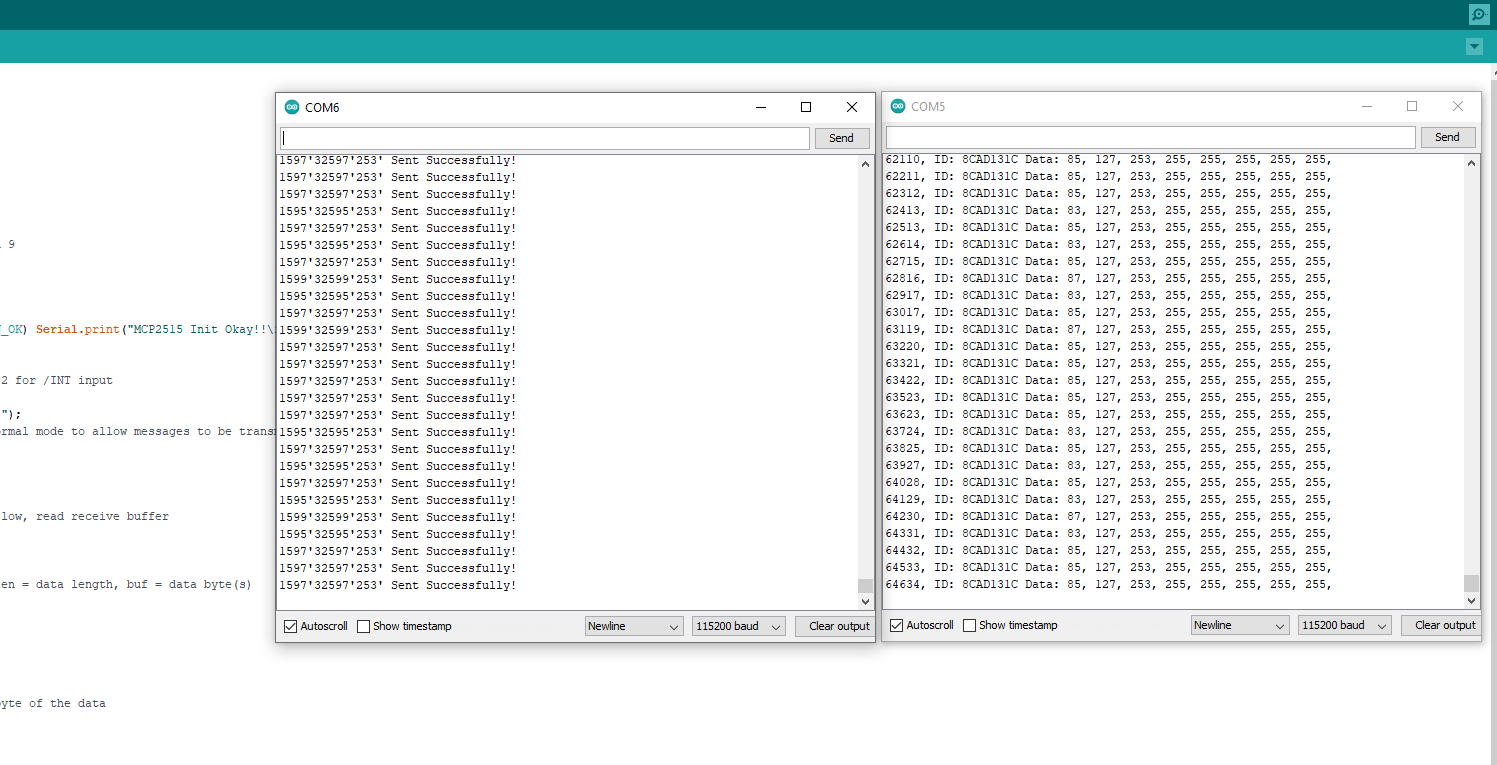
I finally got time to put together the package of Arduino Uno + MCP2515 + Adafruit BNO08X. Here is a screenshot of Arduino IDE Serial Monitor with everything uploaded.
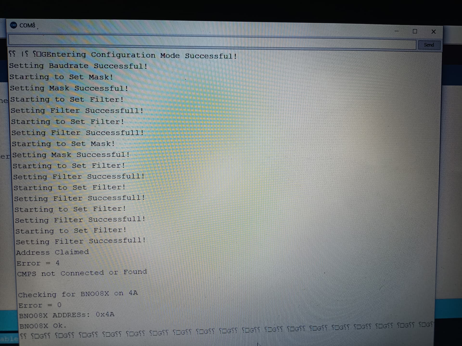
Is this at the bottom what you are referring to as funny text after BNO ok? BNO works in AOG also, so I suppose it’s just plug in and tune for Valtra S274. Great!
Yep looks good to me.
You have two programs the screen shot is from the Arduino without pot & switch, you have set the CS pin and it looks like it is working it will just show messages that are there (but there isn’t any)
So the problem must be in the Arduino with pot & switch, what program have you loaded on it? Have you also changed the CS pin in that program? Make sure you check the first few lines when you first open the serial monitor.
I think i got it, thanks for all the help. I did not set me CS on the other ardunio to 9. Now to try it in the tractor.
Thanks again for the trouble shooting help.
2 Likes
Hello, I would like to control the CAN valve on the New Holland T7.230 TMR. On the Arduino Uno 1 with potentiometer and switch, I have the sketch “Case Puma Tester”. On the Arduino Uno 2 I have “Show all Can Messeges”. I veined the CS pin to 9 and can see what is working.
Now I want to do step 4 and test it in the yard. Which sketch have to be adapted now, Arduino Uno 2? Does that have to include the sketch “Case Puma Simulator”? Or how do I have to do that in order to control the tractor with the quick test potentiometer?
Thanks for the answer
Just make sure its a CANBUS steering valve and if you have factory GPS reciver and Nav Controller unplug them.
Then all you need is the Uno with pot & switch “Case Puma Tester” program, connect the CAN wires to the diganostic plug down low behind the seat Pin-H = CAN-H, Pin J = CAN-L.
Start the tractor, power the UNO (via USB is ok, or power supply), turn the factory steering switch ON, move the steering wheel (to show the SASA sensor is working), drive forward slowly and try the switch & pot.
If it wont work then we can use the 2nd Uno with “Show all messages” to see why it wont work, but if it sends a message on the bench test it normally works in the tractor fine.
I have it running now with the test potentiometer. The problem was also that the tractor is pre-equipped, but the NAV controller was not configured because it did not have one at the factory. Error 15994 was always displayed “NAV detected but not configured”. I activated the Nav in the UCM, now it’s running.
The next step is now to control the CAN via AGO. Have you already been able to read out the factory activation switch for activation and include it in the sketch? That’s not exactly my forte.
Or does it work via PD 6 Steer Switch?
Does your sketch only work for U-Blox with CMPS or also with “Dual” BY-NAV?
1 Like
That’s good, I have not looked into the factory switch via CAN yet in the CNH brand. You can use a button on PD6 or no button and just tap the AgOpen tablet.
The GPS is on its own direct to AgOpen tablet so use what you like (dual is more stable witch helps with lighting fast factory steering valves)
You can use the Uno and CAN shield you have via USB to tablet. Or if you want more you can put a Teensy PCB together and use UPD / Ethernet with the Teensy you can also connect to the ISOBUS too and use that information to control the work switch etc (hitch height, PTO speed etc)
Hello. Somebody tries connect and make autosteer fendt com3 models PVED-CC valve ? And how to get WAS and steering wheel encoder data from isobus?
You have two options:
1 - Remove the Fendt steering controller and replace with AgOpen and control the PVED-CC directly (Left / Right) like @nut has with his programs. With this setup your Arduino reads the WAS voltage and it drives the valve to get wheels where they need to be.
2 - Keep the Fendt steering controller and just connect to the Valve BUS (older Fendts use G-Bus for the valves) with this setup you just send the steering controller where you want the wheels and it sorts them out for you any of the Fendt programs should work.
With option 1 you need the WAS direct (Analog 4-20ma), option 2 AgOpen won’t need the WAS but it is there on V-BUS/G-BUS just for operator reference.
You can try the Fendt programs to test option 2 easy enough, @Alan.Webb said it worked on a 820 fine.
1 Like
It’s now in the distribution package with v5.4. There’s also possibility to do a mix, leave the steering controller in place and read the WAS from the bus.
It’s only Teensy tho isn’t it? What about the Nano program with only CAN valve everything else standard AgOpen?
They’re both in there, the nano program has the capability to use either J1939 WAS or analogue. Needs some fiddling with the PGNs etc but shouldn’t be a big deal to adapt to read from tractor bus.
I’m running it now, but now I have one more question. Can I also change the aggressiveness in the sketch? Since the tractor now steers very aggressively, drive with a single antenna without CMPS. When I drive at 3 km / h it steers well, as soon as I get faster it makes too many and too wide steering movements and swings up. Have all options in the steering settings, but do not get a good result.
This is the problem with factory valves, they set them very fast because they have very stable GPS systems, AgOpen needs to be stable.
So you will need to mount a CMPS or BNO08X, even better dual antenna.
But also you can adjust the “MAX PWM” this controls the maximum allowed set point change per Arduino cycle that’s getting sent to the CANBUS, so by lowering this (say to 150, or lower) it will slow the wheels down.
Other things that can help:
- make sure your counts per deg are set so hard lock is around 35deg (starting point, adjust up/down to suit steering performance
- push the “look a head” out to 3.5m or more
- put the single antenna fwd/rev settings to zero (normally 0.15 & 0.30 as standard)
1 Like
I think the main issue here is lack of an IMU. I run with a heavy imu bias on heading, pretty much no roll filter and very short fix to fix value of 0.5m.
Look ahead I alter depending on the job but usually 3 to 3.4. Look ahead gain around 2.
Tbh I’ve never altered the max pwm but maybe the NH install is different to mine?
1 Like