I’ve been working on setting up an AIO micro board to use with the case 235 hydraulic steering. I was able to get power to the board via the 40pin but not much else.
If anyone has some pictures of their wiring that would be much appreciated.
I’ve been working on setting up an AIO micro board to use with the case 235 hydraulic steering. I was able to get power to the board via the 40pin but not much else.
If anyone has some pictures of their wiring that would be much appreciated.
Have a look at other new holland/case threads.
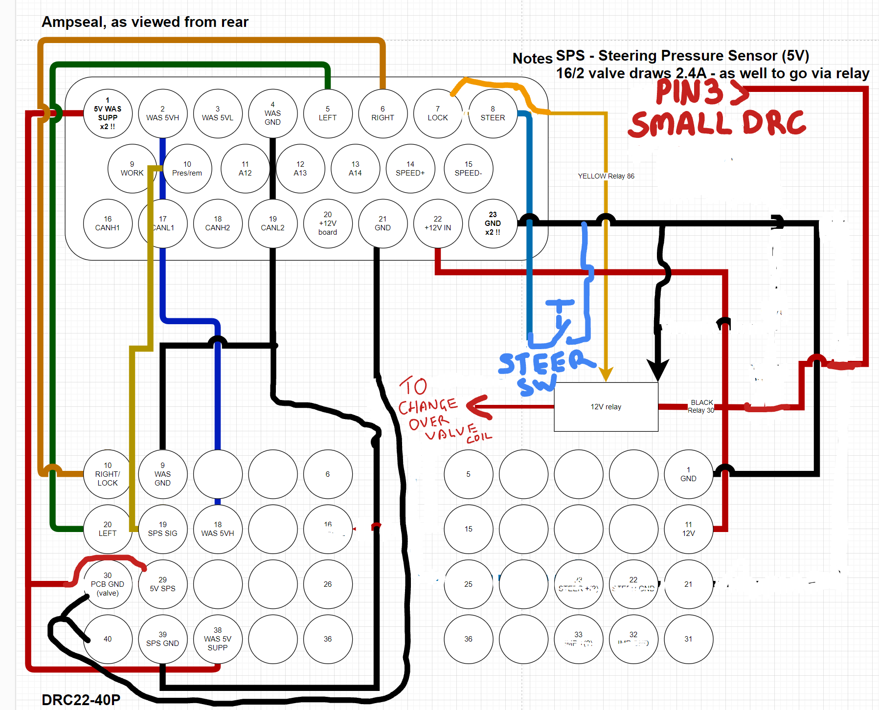
Pin put for the 40 pin connector was linked in a different thread
You might also need to turn the steering controller on in h menu to wake the system up
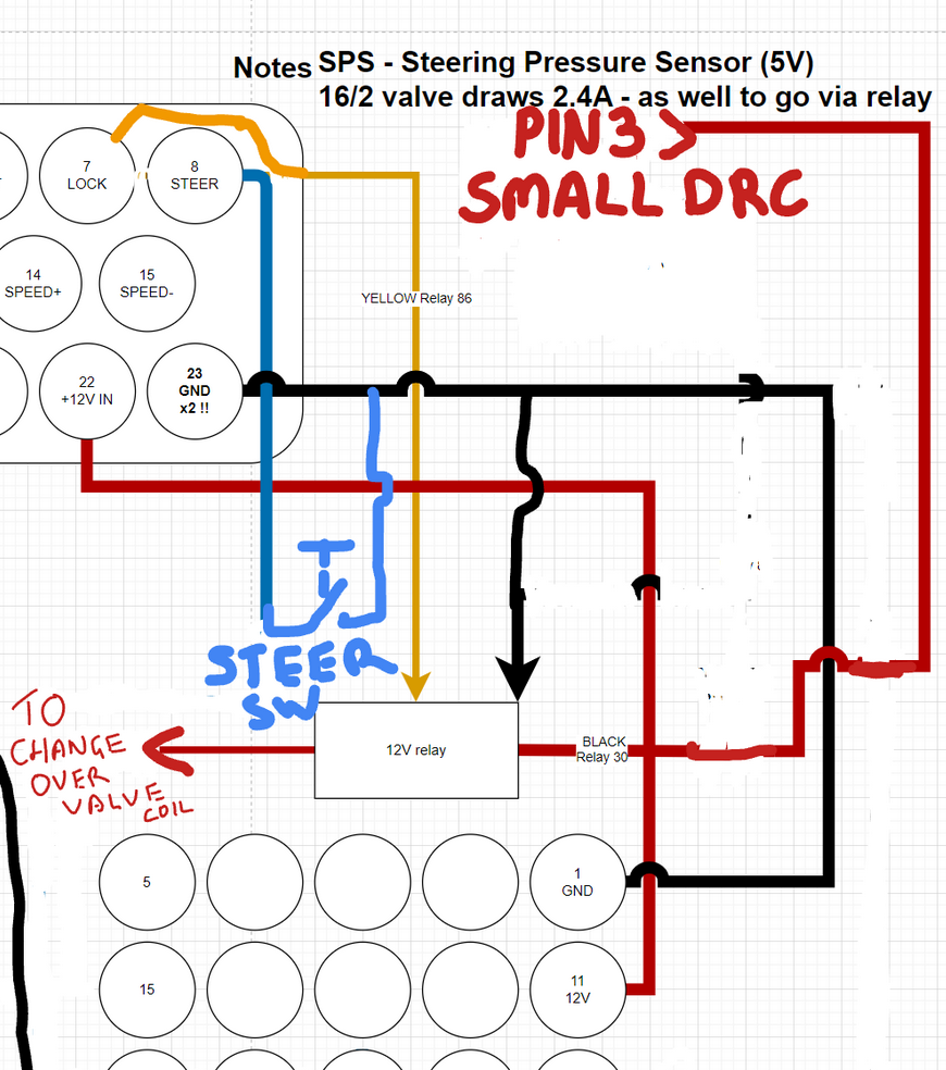
Thank you for showing me that. It seems that many of the images from case 230 success stories are either from older PCBs or have been lost to time.
I notice on the diagram it mentions the “small DRC” which I imagine refers to X952 Universal Controller for the case 230.
I’ve tried to look for that on the 235 but to no avail. What I did find though is a 24 pin connector 409M To Nav Controller Port B. I don’t have the pin out for this but would this be what I should be looking to use in addition to the 40 pin?
You have the 40 pin behind the panel behind the seat correct? And your tractor is steer ready?
Yes the 40 pin is behind the panel. It’s where I got power to the AIO (based off of diagrams shared for the 230 and new hollands). The tractor has valves already for autosteer.
I have also been working on this on a T8500 and it should share the same harness. My recent post is here. I have some of the diagrams that I have on it there. I have not put it in yet but I did attach the pin out in mine. There is also a thread that I referenced in my first post that has a lot of good information with another that worked on his Case 230 that is really good as well. There was also a person about half way through his thread that posted a decent diagram. Its for an older board but should be able to tie it together.
Couple of things to watch out for. The wheel angle sensor on the T8000 series was different for me. Mine has 6 wires and has a separate power, ground, and signal wire for the auto diff lock and autosteer. On the Case Puma 230 in the other thread it shares the same signal wire and there is a plug by the radiator that he splices a Y for the signal wire to share between the two.
The other is that almost every wire is at the 40 pin except for the pin to activate the hydraulic valve. I bought the factory service manual and found out it goes to the transmission computer. On the puma thread he finds it on his Case in a different harness plug and then just pulls the pin and extends the wire. I am planning on just bypassing it and running my own two pin of positive and ground to that plug on the valve.
It will be some time until I get digging into this one as I am currently working on our planter tractor instead but I do plan to try to get this one up in the next couple of weeks. Plan on reporting later on how it all goes. Hope this helps some.
Definitely helps, thanks. I should be out this week so I’ll let you know what I can find.
We were able to get the sensors to work, but we are having trouble understanding the steer switch and valve coil setup from the diagram.
It looks like that is a new steer switch, not the factory fit one.
And it looks like the change over/lock valve is wired to directly and not using the 40 pin harness.
How did you get on connecting to the tractors autosteer system after?.
What pcb did you use. Any pictures of how you connected to the 40 pin connector
Sorry for the delay in response. I used the micro AIO V4.5 which seems to be handling everything fairly well. I can’t speak on the specifics on how to wire the motor itself, as it was done by someone else. I will try to ask him to see if he has any diagrams on how it was done. Aside from that I essentially followed the aforementioned wiring diagrams, using the GPS switch that came with the tractor on the right-hand side. I’ll try to go get some pictures of everything soon.