I have a T8 new Holland that is steer ready that I am trying to figure out if I can utilize what is already there. I did find the success story that matches up on the Case 230 bellow but either the links are dead or some reason I can’t see or download them.
I was able to figure out some of the pins outs needed from others in the thread but I am trying to figure out where the steering engage valve wire is since it isn’t on the 40 pin. Or maybe there is an alternative way to go about it? Thanks.
All pictures on discourse from before mid 2021 is gone forever.
Links to stuff on OneDrive probably need you to logon to OneDrive. But they are all still there.
Links to stuff that is already sold, on eBay and the like, obviously no more work.
I think the steer pin wire is on the other plug that goes with the 40 pin connector.
On the canbus installation the nh needs 2 canbus. One for the was and steering and one for the engage button on the joystick.
There is a diagram of the pinouts for that 40 pin connector and the one thats with it but im struggling to locate the diagram myself
Can definitely understand with the links being so old they might be broken. One drive just says they are missing.
This is a 2010 T8050. I believe it would have had a Nav II box if it would have come from the factory. In my searching I found out in an agleader installation manual it covered the T8000 series and case machines including the 230 and is how I got to the correlation so far. Also in their manual they have a two pin connector that runs to the steering valve to replace a factory connection on it. The installation manual does not really say the purpose of it but I am thinking they decided to just bypass the harness all together to get to that valve instead of messing with finding the other end of the pin like mentioned in the other thread. I also have had a harder time finding the pin out diagram at least freely available.
Thanks for this as I missed your post in my search. I read through it and it is making some more sense. I also see your Nav sheet in one drive and that also helps fill in gaps. I see the sheet you have on the X710 connector and it says it is on right hand side of trim. I suppose the trim of what? Inside the cab?
I am starting to think of picking up a shop manual for this. I took a picture of my 40 pin and the wire numbers and colors are not matching up to your diagram. At least I hope the manual will give me peace of mind that everything is connected right and give me an idea where everything is. Plus it will just be nice to have for other things as well. Thanks for your help. If I do get this all working I plan on sharing with the community.
Yes at your right foot and knee. open right door take away trim, and the cut off relays and x710 is there. X710 about 15 cm above floor, 3 relays bolted to right side around 50 cm above floor.
But don’t do what I did with 710, only reason I did this way was I could not find 3168 at the tractor ECU behind seat as fivefinnishfarmers did, so go the fivefinnishfarmers way, much easier. Also today PCB v4x can handle the pressure sensor directly.
In his thread at around post 70 you also find a stl for the 40 pin connector. I advise to read all posts from there to the end.
Awesome and thanks. I will have to look for it for sure. I did buy a manual online so I can at least check everything as well. Just waiting for it to get sent to me. I would do it the way fivefinnishfarmers did but well I can’t see the image. I will have to look but I don’t remember seeing an ECU back there but I may need to pull some things up to find it.
So just replying in general that I spent some time on this and it seems it is called the Auto Guidance Valve in this manual and I am fairly sure this is what I am looking for. It looks like it goes directly to the transmission computer and it looks like it is outside the cab under the rear window. Kind of convent but I am debating on if I want to mess around pulling out the pin and just do like what the other company did and just run a new line to bypass it all. The manual tell me the connector type of DT06-2S-PO12 and looks pretty easy to get. Need to find the connector port itself though.
Also another interesting thing is the WAS is not split on this like the the Case 230 but the sensor itself is a 6 pin that is 3 for auto steer and 3 for what I am assuming is the diff lock. Each require there own power and ground and provide there own signal. Maybe they tried to simplify it later on.
You should read the name and number on the was, as there’s several different was types with 6 pin.
Also provide pictures of tractor, as age 2010 suggest it is not a T8 series which came out late 2014.
Also pictures of cable connectors from the used autosteer on tractor.
Often you can find instructions for cabling in the manual to the previous autosteer system.
Please also a picture of valve behind rear window.
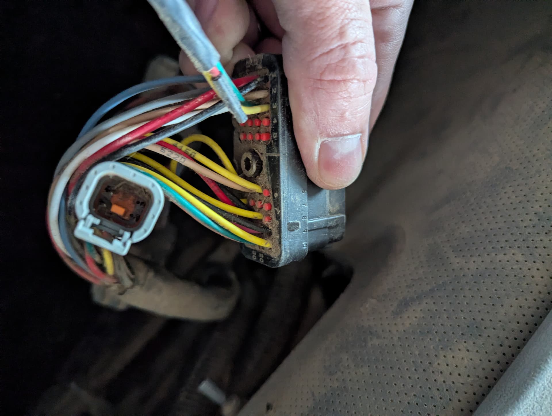
Sorry I miss labeled this as T8 but it is a T8050 and the T8000 series are a little older. I am not always on the farm as I have a regular day job and it is dark by the time I am off work yet. Consistently bellow zero probably till the end of February too and no heated shop so puts a damper on digging into it right now! Main thing was just to get research while I was waiting for my AIO order to come in. I did get a picture of the 40 pin connector the last time I was there trying to compare to other pin out diagrams. Not a great picture but you can get the idea.
I didn’t realize the wire numbers at the time but I did match up the one wire number that I can see in the photo so at least my manual should be correct.
Here is a diagram of the auto guidance wiring in the manual. This page also happens to have the WAS in it right bellow as Steering Sensor. The transmission end isn’t in there but I did confirm that the transmission plug is connector 355M. Unfortunately it isn’t easy to get to the WAS. The bracket for the front fender sit right over it and is pretty tight on top off it. I probably can pull the plug though to look at the end though.
I will see if I can get to the transmission controller and see if I can find the steering valve as well this weekend.
I see many of the wires match the T7-175 40 pin plug. Your cable numbers are 3 digit plus a letter, and they are mostly 4 digit in T6-175 schematic.
The PDF I have, have longer names at pin descriptions, could help get the meaning of yours. Example pin 40 (which is same function in both) on yours look like it say S.V. LI LOW but by copying it from your pdf the T come out like this: S.V. LT LOW
Here is a link to a new pdf I put in the my CNH onedrive folder: CNH pin40 page 2731.pdf
There is something odd in your schematics (I believe wrong) If you follow pin 20 wire 982 (S.V. LH) you end up at security relay controlled by wire 177 and switch at Frame 27.
If you follow pin 10 wire 419 S.V. SOURCE you end up at the other security relay controlled by same 177 wire.
This means 10 and 20 do the exact same both in your schematic and my schematic.
Also I believe your pin 30 wire 410, should be renamed S.V. RH LOW (same way as your pin 40 is named for Left.
And then 10 should be renamed S.V. RH (as your 20 for the left feed)
I believe your Cut Off valve is named TO AUTOGUIDANCE VALVE (found in your frame 72 ) controlled by somethinf in frame 37 ?
Here is the 407M connector in the manual that would compliment your sheet.
I agree with what you are saying. I think the labeling on the diagram is a little wrong. Looking at the pin out on the 407M connector it looks more correct. And I am glad you agree as well on the Auto guidance Valve being the pin I am looking for. If you go to frame 37 it does go to to the transmission plug.
I was also thinking what that switch could be for wire 177 but I think it might be referring to the manual shutoff switch for the entire tractor.
It seems wire 177 and 179 are all Black and goes to GND so maybe just a connector ?. (also you are right the other end must go to transmission ECU which can feed 12 V to cut off valve, making it logical to say 177 is GND (double check with multimeter)
345B R- 0.8 (with green colored wires) in frame 73 must be your autosteer manual switch, placed somewhere in the cabin. Also (when ON) activating security relays and feeding pin 3 in the 24 pin connector, beside the 40 pin connector.
Hey @Larsvest. I am looking at this more again and I was just trying to figure out where the dump valve or in my case auto steer valve wire would go onto. Would that just go on the lock pin? I am working with the 4.5 micro. I think I am right but questioning my logic.
Also I missed that the pressure sensor needs a 5V connection. Should I just share the 5V with the WAS? I just wasn’t sure if there were any problems with it being always activated. Just trying to figure out what is different from the older boards over the 4.5 boards and if they have stuff built in that the older boards didn’t have.
Working on getting a different tractor going this weekend and if all is good will start working on this one soon.
Yes 5v was is fine. No problem feeding constantly.
Basically older PCB work like never PCB, just with more features like a pressure sensor input. And off course a teensy capable of running panda directly in the INO.
On the T6 175 I worked on the wires from valves goes under carpet just under pedals from left to right, and into the room at right knee. There it reaches the 3 security relays, mounted together and quite high. 2 relays cut the wires from autosteer controller to left and right steer valve (check wire numbers) the third is controlling the cut off/block valve, so basically you can just shift the 12v control wire on that relay…
In your wiring diagram in Frame 72 it say that the autoguidance valve/cut off valve has wires in Frame 37. Go there to chech which wire number, and which relay…
Or check wire numbers at the valve, and work your way back to relay, they all keep numbers on the T6 175 but colour might change at relays