The time has finally come where I am happy with the autosteer and am finally getting around to adding tool control.
Really basic question: I’m using PCBv2, do I need a single LM2596 board to connect this to an 8 relay control board? Looked around for circuit diagrams, but they all seem to be from before the migration to the discourse board, ergo all images are missing!
PCB V2 has a loaction where you can get 5V for the Board and Nano. Given both are in the same housing.
I think I need to add the LM2596?
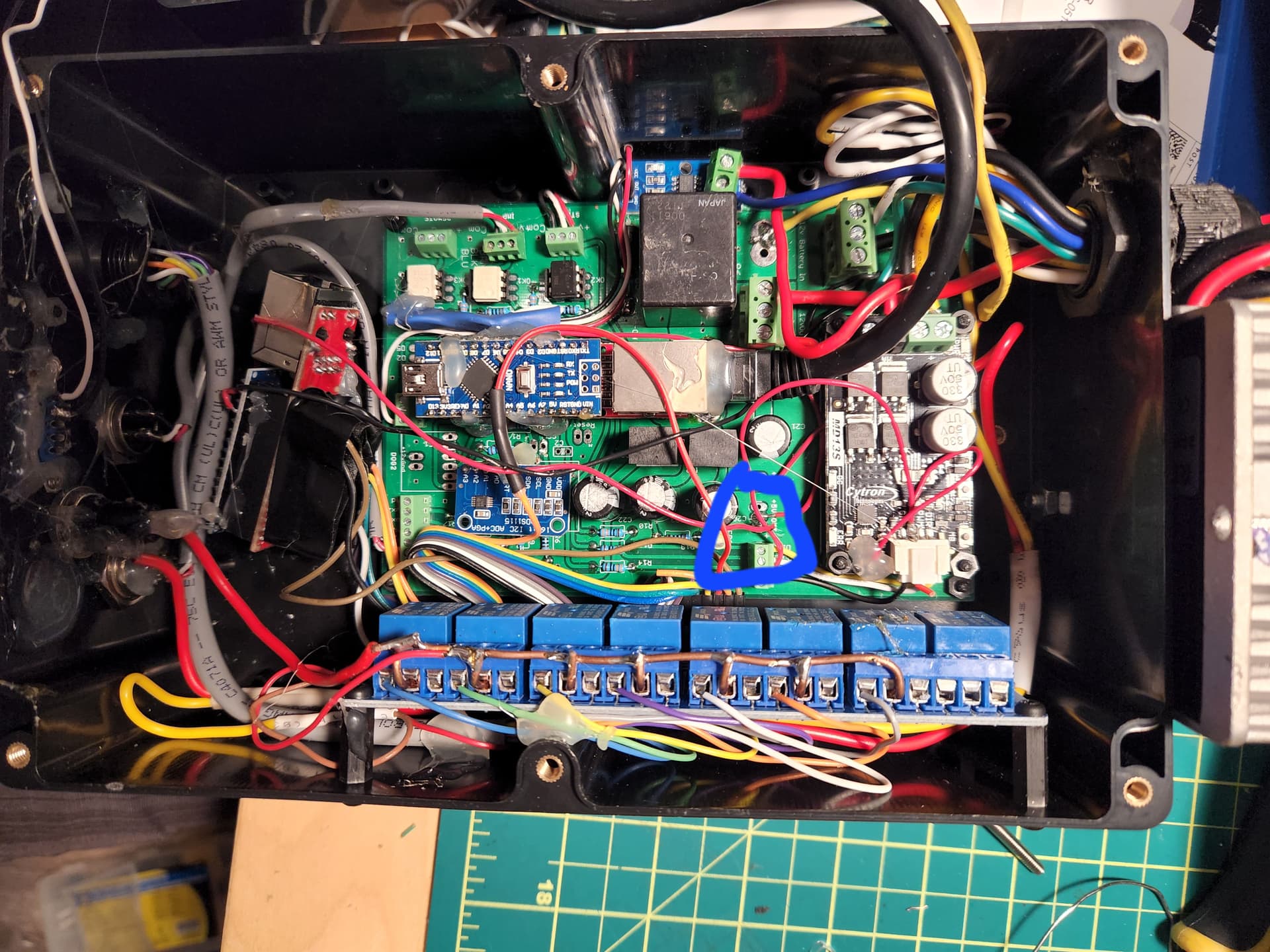
Tje LM2596 is a buck converter set to 5V supplying power to the Arduino and reelay board. The PCB V2 has two 12v to 5V buck converters installed already. You can use the 5V if you want. Here is my box fron the inside. 5v is circled.
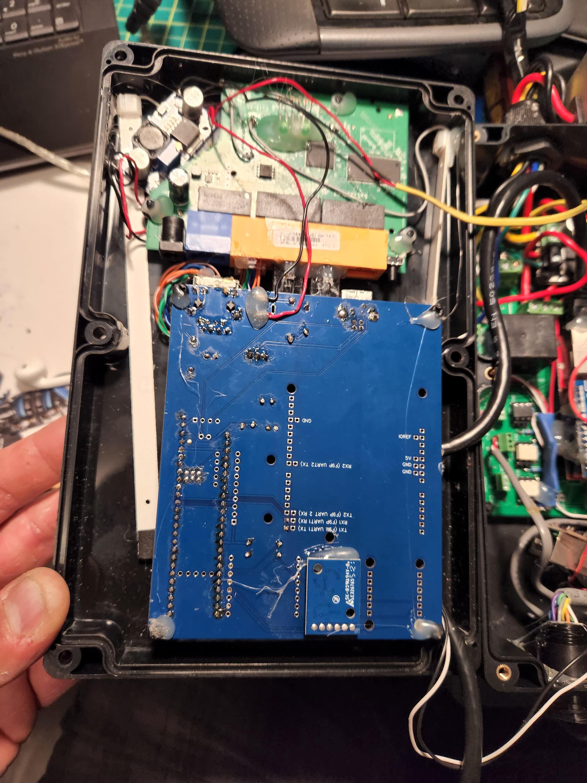
This is the lid.
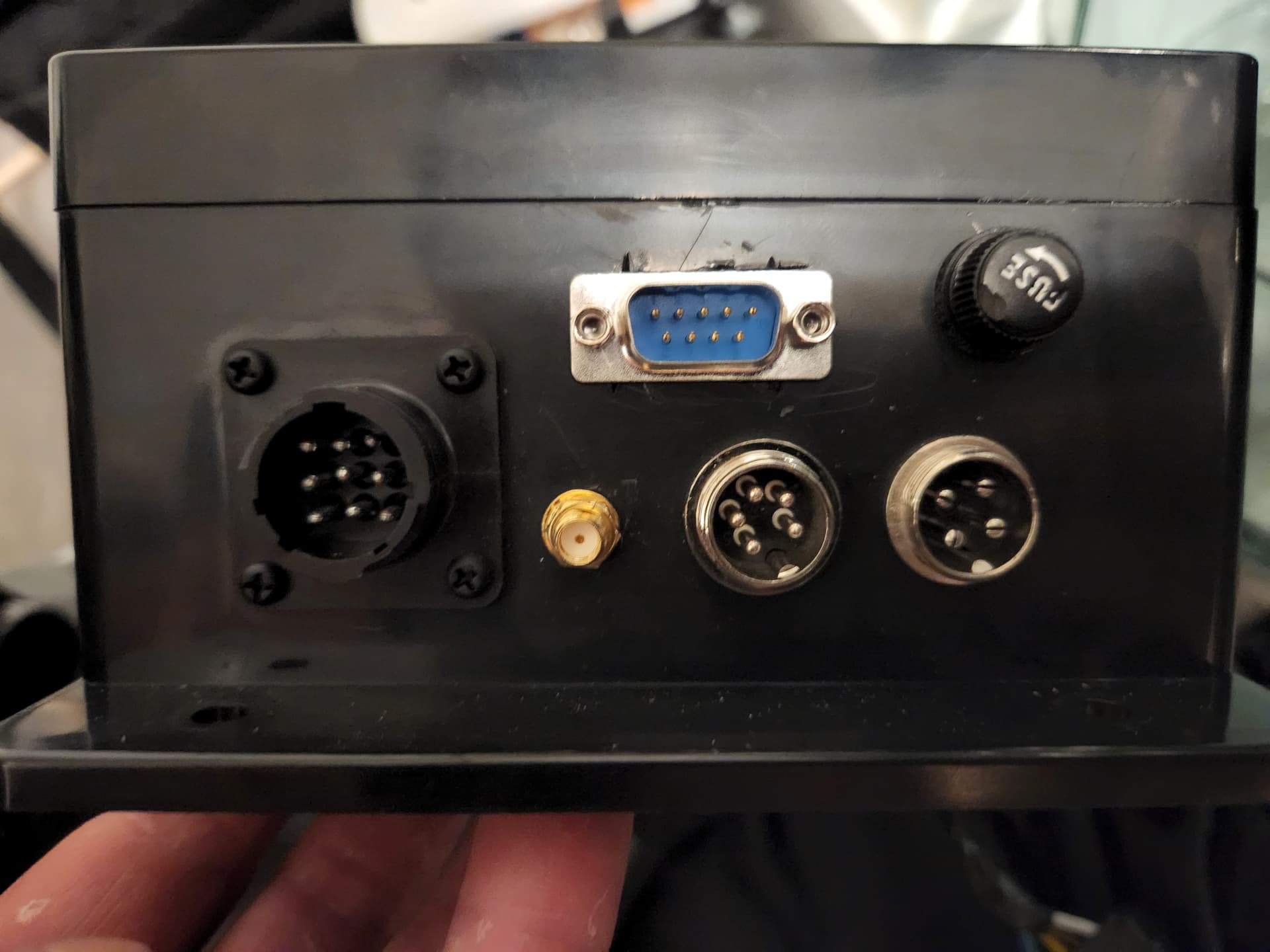
Front
4pin= WAS
5pin = implement
9 pin = relay board
Dsub 9 pin and SMA are for antenna
1 Like
I’m still a little unclear on this.
I have the same 5v outputs as you so I can connect this to the relay, but that’s just power. Where are the relays getting their signal?
Are you literally just attaching power, or are you connecting anything else to the relay board?
The relays get triggered by the Arduino Nano.
The schematics are in the support files.
MachineUSB_Schematic.zip (2.0 MB)
1 Like
I’m just looking at your board. Have you hot glued wires from the nano pins to the relays?
Yes, i use hot glue. That way they don’t come off. To remove them i use freeze spray. That cools glue down, then you can remove it easily.
I had made a stupid mistake and thought the IMP switch port connected to the relay board.
Got it now thanks for your patience.
I think the usual method is to just use a separate Uno 
1 Like
CORRECTION - The REMOTE counts impulses to disengage auto steer.
IMP is for the implement switch.
Sorry
I’ve been using AOG for a few years now, but only for autosteer, not tool control (outside the simulator).
Just getting into the tool control now and starting to appreciate how powerful AOG is.
1 Like
I’d assumed “Implement” / section control.
Stupid of me because I’d built the Uno / relay circuit a year or more back for the Section 8 geofence killswitch feature that @KentStuff added, and had this working with the simulator.
Meant to add this circuit, but then forgot
It would be much easier if there was a port on the PCB for section control. Love your solution.
1 Like
Sorry, i was wrong IMP is for implement switch. Remote ist for counting impulses.
1 Like