DIY PWM nozzle and rate control

This is a topic to continue @whiterose’s discussion of PWM implementation and rate control, with the goal of operating it under AOG.

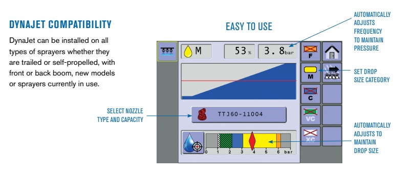
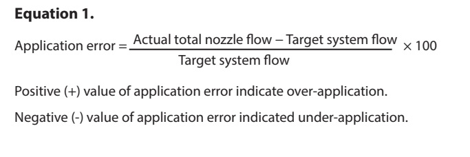
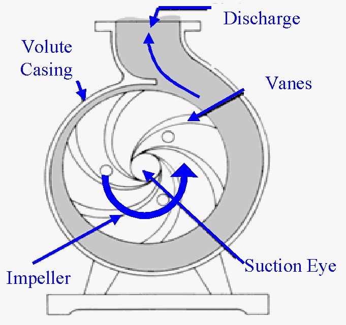
I can tell you how it works on a commercial system using a hydraulically-driven centrifugal pump. A pressure transducer on the boom measures pressure. A PID loop controls the hydraulic flow to the pump and tries to maintain a pressure set point at the boom. As nozzles open up, the pressure will drop, and the PID loop will increase the pressure to compensate. This is a closed-loop system and depends on no other variables, nor does it care what the nozzle size you are using is. Although it might be possible to “prime” the PID loop with some of that information so that it settles in more quickly when you first start it up.

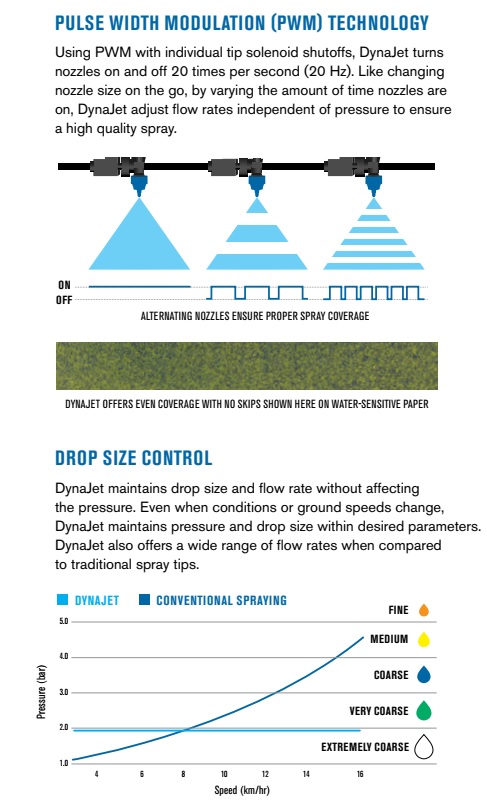
Rate control is done with a flow meter. This has its own PID loop. The input is the current flow rate, the set point is the desired flow rate (more on this below), and the output of the PID loop is the duty cycle of the nozzle solenoids. In other words if you want flow of 50 l/min, and the current flow rate is 40 l/min, then the PID loop will increase base duty cycle of the PWM nozzles. If the flow rate is too high, the base PWM duty cycle must be decreased.

The flow rate is calculated based on how many nozzles are open (the total coverage width of the open nozzles), the rate per area desired, and the travel speed.

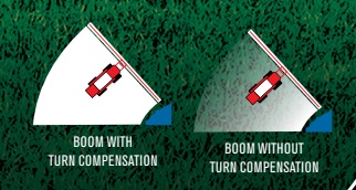
Figuring out the PWM duty cycle for turn compensation is quite easy. If the center of the boom is the base PWM rate, the other nozzles are either plus or minus that base rate, depending on the distance from the center and the yaw (turning) rate.

The catch with turn compensation is calculating the flow rate needed for the above PID loop. That gets a little tricky. Or at least it means you have to start doing per-nozzle calculations to try to get the full flow rate. These calculations require knowledge of the calibrated flow rate of the nozzle. (Actually I’m not certain of that… it might not even require that information.)

I’ll try to post more actual numbers later. I’ll do some calculations.

4 Likes

A search of “Arduino read PWM duty cycle” turned up quite a tutorial on " Secrets of Arduino PWM - Learn about Pulse Width Modulation techniques". A good reference to get up to speed on PMW.

1 Like

Thank you for your valuable reply. Based on what you wrote, I did some research and thought that this system is a really useful system, I added a few photos for other friends to benefit from. I’m confused about a few things:
1-) If we have to specify the nozzle we will use to the system, the hole of the nozzle will give wrong results in case of enlargement. (pressure operated system)
2-) If we use a flow meter, I think there is no need to introduce the type of nozzle to the system, I hope what I wrote is correct.
3-) Is it the right way to connect and operate the nozzles with can-bus to control the nozzles independently and set the duty separately?


2

4

With a flow meter to get actual and a target for goal, nozzle selection will have nothing to due with the rate (within limits) but will determine droplet size.

1 Like

Yes that is true. And if you are making an integrated, DIY rate controller and PWM system, I don’t think you need any knowledge of the nozzle type (although they must be all the same size).

PWM add-on systems like TeeJet and Capstan do need to know what nozzles you are using, however. But that’s because they are add-on systems and they drive your existing rate controller. A bit hard to explain why but I’ll try. Normally the your existing rate controller knows only about sections, not individual nozzles. It’s used to turning off entire sections, not one nozzle at a time. So the PWM system can shut off one nozzle at a time and as it does that, flow rate diminishes so the rate controller would normally try to compensate and bring the rate back up. But that would lead to overs-spray in this situation, so the PWM add-on system calculates, based on its knowledge of your nozzle sizes, what the flow rate would be if all the nozzles in a section were on. It then sends that faked flow rate to the rate controller so it won’t try to turn up the pump as the nozzles shut off. Hope that makes a sort of sense.

In a fully integrated system, that is not necessary as since the rate controller knows about each individual nozzle it can calculate the flow rate based on simple coverage width. I’ll post some equations that show how that works.

3 Likes

See the last two replies

Yes I’m pretty sure that is correct.

I’m sure you could. Commercial systems use CAN to tie all the controllers together. My Capstan system has 9 control modules that each control between 5 and 10 nozzles. They are all connected to a common CAN bus. But in my mind this is what they call a “implementation detail.” First a rate controller must be fleshed in terms of computer code.

1 Like

You explained it so well that I couldn’t even find this information on google, I’m grateful. I was planning to check the nozzles one by one, but as you said, I have to check it section by section. I can define an address for each partition and control it via CAN. Only your opinion about the pump is important to me, is it a centrifugal pump or a diaphragm spray pump as you say? I understand that you recommend the centrifugal pump because it has high flow and low pressure, as far as I know, membrane (diaphragm) pumps used in pesticides also work with high flow but high pressure.


indir

We like high pressure, uses less chem, about 110 psi (8 bar) and we use a diaphragm pump for that.

If the nozzles were controlled in opposite pairs during a turn (inside reduces, outside increases) could the controller assume the average is the same as what the middle nozzle (base rate according to speed) is doing and still know the target flow rate? Maybe you were talking about flow in a turn with some nozzles turned off, that would be a bit trickier.

2 Likes

A diaphram pump can work. But they are positive displacement, so you have to use a diverter valve to redirect unwanted flow back to the tank. You have to control 2 variables together. The speed of the pump, and also controlling diverter valve. I’m not sure how to do that! I’m sure it’s possible though!

2 Likes

So the math is quite simple, actually. Here is a small Python program that defines two functions that can be used to do all the calculations. One function calculates volume per minute given a travel speed, a desired volume per area, and the width of the application. The second function calculates the effect of turning on travel speed. This results in a percentage that can be applied to all other parameters including the flow rate of a particular nozzle, or the PWM duty cycle.

Here’s how you would do the math to get a total flow rate:

  • Calculate a single nozzle’s flow rate per minute
  • For each nozzle that is on, calculate the percentage effect of turning, and multiple that by the single nozzle flow rate
  • Add up all the resulting flow rates
    Feed this total flow rate to the rate controller which will adjust the duty cycle to achieve this if it can.

You really only need to calculate the turn compensation percentage once, and it applies linearly across the boom. In other words if you find a turn compensation factor at postion X, then at position X * 2, the factor is also doubled.

None of the math involves the nozzle size since we’re dealing with flow rates. If you have set a particular pressure and you try to drive too fast, the rate controller will try to achieve the flow rate by increasing the PWM, but once the PWM duty cycle hits 100% it cannot do any more, so your sprayer will under apply. Most systems give a warning when it can no longer achieve the desired rate.

My code works with km/h, metres, litres/ha, and results in litres/minute. But for us old fashioned north american people, I have conversion units to use the units I work with as well.

"""
A small collection of basic functions to perform sprayer rate control
calculations
"""

# constants for converting units

SQUARE_DIST_TO_AREA = 10000 #10000 m^2 per hectare
DIST_CONV = 1000 # metres per km
SPEED_CONV = 1000 / 3600 # km to m/s

# helpers for us backward folk
HA2AC = 2.47
GAL2L = 3.785
GPA = HA2AC * GAL2L #convert GPA to L/Ha
MPH = 1.609344
INCH = 0.0254
GPM = 1 / GAL2L

def nozzle_flow_rate(speed, rate_per_area, width):
    """
        Calculate volume per minute of flow given a travel speed,
        desired rate per area, and the width of the nozzle's
        coverage area.

        speed is km/h, rate is l/ha, and width is in metres
    """

    # in one minute, how much area is covered by this nozzle
    area = speed * SPEED_CONV * width / SQUARE_DIST_TO_AREA * 60

    # multiply by the rate per area to get volume per minute
    return rate_per_area * area

def nozzle_turn_compensation(speed, yaw_rate, distance_from_center):
    """
        Calculate relative speed of the nozzle's travel during
        a turn.  Returns a percent relative to the center of 
        the boom. This percentage applies to all parameters including
        calculated flow rate and PWM duty cycle.

        speed is in km/h

        Postive distance_from_center values are right of center
        (starboard), and negative values are left of center (port)
        when facing forward.  Distance is in metres.

        yaw_rate is in degrees per second, and positive value means
        turning right, and negative value means turning left.

    """

    speed_per_s = speed * SPEED_CONV
    speed_difference = yaw_rate / 360 * -distance_from_center

    # return a ratio (percentage) of the compensated speed to the 
    # travel speed of the center of of the boom which isn't turning
    return (speed_difference + speed) / speed

print ("8 mph, 5 gpa, 20 inch wide is %0.3f gpm flow." % (nozzle_flow_rate(8 * MPH, 5 * GPA, 20 * INCH) * GPM))
print ("8 mph, 120 deg/s turn right, 410 inches out, ratio is %0.02f." % (nozzle_turn_compensation(8 * MPH, 120, 410 * INCH)))
print ("8 mph, 120 deg/s turn left, 410 inches out, ratio is %0.02f." % (nozzle_turn_compensation(8 * MPH, -120, 410 * INCH)))
1 Like

That’s how the Amazone rate controller works AFAIK, there’s a flow meter to and from the boom and it calculates the difference. Flow meters aren’t too bad priced, like 90 eur / piece. You control then the pressure regulator with the PID loop to keep the flow constant and adjust the flow demand depending on how many sections you have open.

There’s a few commercial controllers out there that pack 12-16 PWM outputs into a small form-factor J1939 package, those might be bit more robust than some arduino etc. as they need to hang on the boom to keep the cable lengths somehow reasonable.

1 Like

At about 6 watts per solenoid, that’s only 0.5 amps, so a controller like this could do it:

(edit: this unit does not look acceptable as it has a minimum frequency of 100 hz, which is probably too high. Most systems use between 10 and 30 hz… the nozzle isn’t physically capable of pulsing much faster than that)

Of course for best coverage results one would want every other nozzle pulsing in sync. Not sure if these off-the-shelf units can synchronize the pwm signal that way.

Mostly they are programmable, so you’d set your own J1939 messages (e.g. one PGN per 8 nozzles, so you got one byte to control the rate 0-255 on each nozzle) and drive the 8 outputs based on that. The hazard is that you gotta buy some proprietary programming tools for those units…

1 Like

Yeah. Anyway my main interest here is the math.

1 Like

Reflecting back to spraying in practice, on headlands the boom is yawing quite heavily if you run into a bumb or turn too abruptly. Should there be an IMU sitting on the boom so that you could run the control algorithm based on the actual motion of the boom, not the tractor?

@nut,

I think that idea has some merit! If placed at the end of the boom it could be determined if you were turning left or right.

Wouldn’t one of these work to send the signal to the relay?

You would need something that can PWM switch at least half an amp at 12V per channel. And have the ability to synchronize the pulse frequency to get every other nozzle pulsing in sync.

The math is the easy part. The hardware is more difficult.

I doubt it’s worth it. By the time you calculate that some tiny change in flow is required, and after the PID loop moves the flow, and it propagates through the hoses, it’s all too late anyway. Boom wag can happen much quicker than any PID loop can react. The best you can hope for is to hit an average I think. Even when driving straight the booms wag back and forth quite a bit. Over a foot on my sprayer. So you’re constantly getting slight over and under spraying. But it averages out and doesn’t seem to matter.