How many sections / nozzles are we looking at??
Something you may consider to get huge benefit for some simplicity is connect 4 nozzles together - or even 2.
For a non CAN approach you can also use these. each output runs on its own and can be set any time to any speed. Downside is 24 hz is the minimum frequency in the built in clock. Overview | Adafruit PCA9685 16-Channel Servo Driver | Adafruit Learning System
But… you can also run an external clock into all the modules, synchronizing them (you can connect 128 of them) and set any pwm freq you want. This would allow every other nozzle to be on when one beside is off.
1 Like
Are you referring to boom movement? My sprayer is 72 nozzles, 120’. The boom tips move around a lot. Plus the whole-boom breakaway system means the entire boom can move up to a few feet if you slow down in a hurry.
On a smaller machine, things are much more rigid and I wouldn’t worry too much about it.
I was asking about the number of. Nozzles. Do we start with 72, 128, 64? I can see what you are saying with the boom movement and timing.
I believe @whiterose has been doing some small scale prototyping. That’s certainly where one would want to start.
1 Like
Is this a special type of clock or just a RTC?
Yes, 12 meters. I’m planning to start with 24 nozzles, thanks for your valuable information.
I don’t understand here either, it says they must all have the same pwm frequency.
Output Ports
There are 16 output ports. Each port has 3 pins: V+, GND and the PWM output. Each PWM runs completely independently but they must all have the same PWM frequency. That is, for LEDs you probably want 1.0 KHz but servos need 60 Hz - so you cannot use half for LEDs @ 1.0 KHz and half @ 60 Hz.
Well sharing the frequency is almost ideal. We do want nozzles to pulse together in time. Only the duty cycle changes. For best coverage, however, we’d like the frequency of every other nozzle to be exactly opposite phase. When nozzle 1 is turning on, nozzle 2 is off, and vice versa. Hope that makes sense. I only glanced through the specs and I don’t readily see the mechanism for providing a clock signal to this board.
I don’t think it’s an RTC. It would be some kind of square wave pulse that would be divided internally by the board’s control hardware. I haven’t found the information on how this clock signal is provided. I see a clock input but I think that has to do with the i2c. Perhaps it uses that as a source clock? If so, then any board attached to that same i2c clock signal would pulse in sync. Not sure how to generate the opposite phase pwm signal that every other nozzle would need.
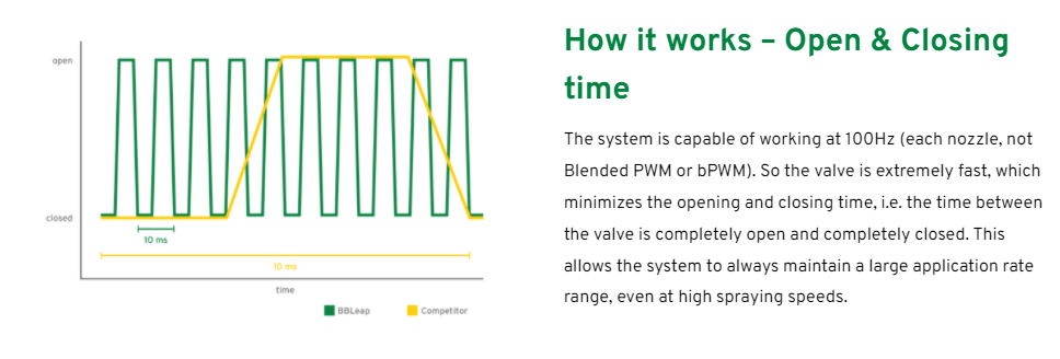
You are so right, I mixed frequency and duty cycle, the frequency will be constant and only the duty cycle will change. Meanwhile, at 100 Hz. There is a system that has a system, I think, to be able to spray 30 - 50 km / h, or I do not fully understand why such a high frequency is needed, and 100 Hz. How did they produce a valve that could work…

Looks good to me.
1 Like
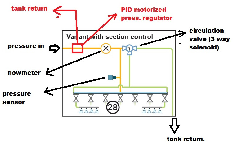
Would you need a second flow meter on the tank return line, then subtract return from flow 1 for actual applied?
I may have found the clock needed. Good thing Google makes suggestions cause I was going nowhere on my own.
I don’t think so. During spraying operation the recirculating valve is closed so all flow goes to the booms, through both the yellow and green lines.
One thing I’ve never thought of before is that when the recirculation valve is open, unless green the tank return line has a restriction in it, the pressure will drop. On a hydraulic pump, that would cause the pressure PID loop to cause the pump to go to 100%. In the case of a diaphram pump it would just mean the red tank return would be entirely closed, which is probably fine.
1 Like
Have you found any information on how a clock source is attached to the PWM board?
Thee best I have come up with is the schematic - It is pin 25 and is grounded. The data sheet on page 14 says - To use the EXTCLK pin, this bit must be set by the following sequence:
- Set the SLEEP bit in MODE1. This turns off the internal oscillator.
- Write logic 1s to both the SLEEP and EXTCLK bits in MODE1. The switch is
now made. The external clock can be active during the switch because the
SLEEP bit is set.
This bit is a ‘sticky bit’, that is, it cannot be cleared by writing a logic 0 to it. The
EXTCLK bit can only be cleared by a power cycle or software reset.
EXTCLK range is DC to 50 MHz
Looks to need a weee bit of a hack!! ![]()
![]()
![]()
(edit) the pin is on the chip it’s self.
(edit 2) It’s got SDA SCL pins so, I haven’t looked at any sample code yet. I’ll do that and get back.
2 Likes
This is close to bottom of the discussion.
“If you’re building your own PCA9685 circuit, you’ll have the freedom to place the signals where you want them.”
My search was - si5351 and pca9685
Looks like back to a hack.
1 Like