Do you suppose it would be so easy as to connect the EXTCLK from the clock to the EXTCLK on the PWM board?
I don’t know. I assume if the signal is 3.3v with a common ground, it would just be one wire connecting, yes.
You already have a clock in the MCU, just set a counter timer and let it run.
2 Likes
Says a lot for Brian when he sees me struggling so bad and jumps in with such a brilliant solution. I’ve seen the timers in the .inos - why didn’t I think of that?
2 Likes
Please note, you are working with chemicals and mixtures of it, so you need industrial standard for it.
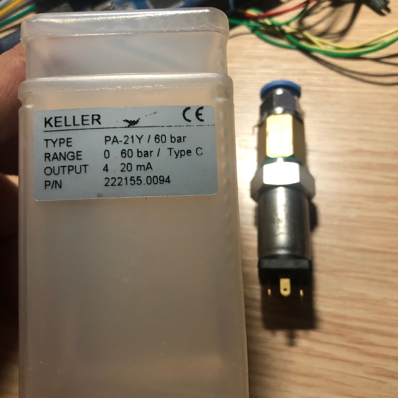
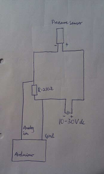
1.6 Mpa = 16 Bar – 0 Bar = 0.5 V. ----- If 16 Bar = 4.5 V. then 4 Bar = 1.12 volts. If the sensor cable is too long, the pressure value will constantly fluctuate due to interference and external factors, and it will not be correct, I would use 4-20 mA in such cases. I use pressure sensors that work with (I use a 250 ohm resistor to use on the arduino), it is not affected by external factors, and it is generally 4-20 mA in industry and agricultural machinery. You will see sensors being used. If you are going to use a 0.5-4.5v sensor, it would be better to take the average value with the software and use a shielded cable.
Do you have a link to what you are using?
I use this, I fix the values with the map command on the arduino.
Or you can use converter like this…
1 Like
I was thinking about the how PWM works on my Capstan 1, and then when talking to my brother he mentioned that it would be nice if you could set a low and high pressure point instead of just a single pressure. In other words a hybrid rate control. PWM would only come into play once the minimum pressure was hit. Basically once PWM hits 100% (full on), then the rate controller would nudge the pressure set point up until eventually it hits the set maximum (to limit droplet size and coverage), which would then have no choice but to under-apply. When slowing down, the rate controller would first drop pressure, keeping PWM at 100%, until the pressure hits the minimum, after which it would start pulsing.
There are a lot of other possibilities of operation, such as combinig nozzle sizes and types. For example you could start spraying with a PWM-compatible nozzle, but once that hits 100%, the system could switch to using standard, non-PWM air-inducted nozzles and a conventional flow-controlled PID loop on the pump again.
1 Like
During the night last night I figured out why my timer code - duty cycle - HZ code didn’t look right. I haven’t touched it for a couple weeks, funny how that happens.
So I think this is working. I have a pot for HZ 1 - 25 and a pot for duty cycle 1 - 255 (1 - 100%). Just stand-ins for sensors to control duty cycle. Would the Frequency ever want to be changed on the go?
#define Freq_Pin A0         // input pin for the Frequency potentiometer
#define Duty_Cycle_Pin A1   // input pin for Duty Cycle Pot
#define PWM_Pin 3           // Hook a LED inline with a 330 ohm resistor to this pin

int Freq_Value = 0;         // variable to store the value coming from the Frequency potentiometer
byte Duty_Cycle = 0;        // variable to store the value coming from the Duty Cycle potentiometer
int Millies_Temp = 0;            // variable to hold Millies

unsigned long previousMillis = 0;
int HZ_Calc = 0;
int HZ = 0;

void setup() {
  // declare the ledPin as an OUTPUT:
  pinMode(Freq_Pin, INPUT);
  pinMode(Duty_Cycle_Pin, INPUT);
  pinMode(PWM_Pin, OUTPUT);
  Serial.begin(19200);
}

void loop() {
  unsigned long currentMillis = millis();

  if (currentMillis - previousMillis >= Freq_Value) {   // Start timed loop
    previousMillis = currentMillis;  // save the last time you were here

    // read the value from the Freq_Pin:
    int Temp_Freq_Value = analogRead(Freq_Pin);
    Freq_Value = map(Temp_Freq_Value, 1, 1023, 1000, 40);  // result in 1 to 25 HZ
    HZ_Calc = (1000 / Freq_Value);
    HZ = map(Temp_Freq_Value, 1, 1023, 1, 25);  // result in 1000 to 40 Millies
    Millies_Temp = (1000 / HZ);

    // Read duty cycle pot
    int Duty_Cycle_Value = analogRead(Duty_Cycle_Pin);
    Duty_Cycle = map(Duty_Cycle_Value, 1, 1023, 1, 255);

    analogWrite(PWM_Pin, Duty_Cycle);
    // end of timed loop
  }
  Serial.print("Duty Cycle = ");
  Serial.println(Duty_Cycle);          // this will show in serial plotter as poor oscilliscope
  //Serial.print("    Millies = ");
  //Serial.println(Millies_Temp);
  //Serial.print("    HZ =  ");
  //Serial.println(HZ_Calc);
For kicks I serial plotted the duty cycle. Worked best at 19200 baud rate. I thought a higher speed would be better. Totally useless info but it does look somewhat like the duty cycle should. I’m looking for someone with a scope to see if it really works!! I think I know someone.
Any other progress?? A couple more months and I can try some of this with the sprayer. It’s way to cold now.
2 Likes
Not sure if changing frequency cycle on the fly is important or not. Guess you’d have to try it. Maybe lower duty cycle would work best at the higher frequencies (less striping), but then again, maybe 20 hz works just as well at any duty cycle. New Case patriot can be set to run anything between 10 and 20 hz (operator decides). At the higher frequency they say the solenoid valve poppets will wear more quickly.
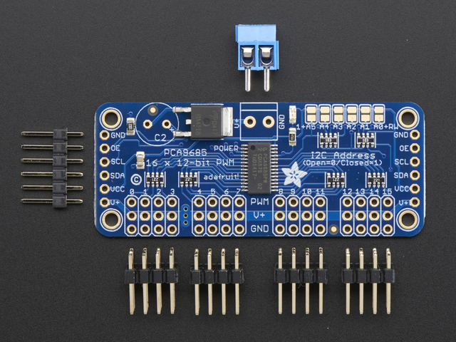
After playing around with this for a while, I have decided that I’m going to base my Machine - Relay PCB on this board. 1 of these gives you 16 PWM pins and you can add 61 more for a total of 992 pins. That should handle all the section control needed by most folks.
The command that makes this work (with Adfruits library) is;
pwm1.setPWM(1, Duty on #, Duty Off #); the pwm1 sets the board (the first one of the 62 possible),
pwm1.setPWM(0,4096,0) setPWM(0 is the first pin, 4096 is full on, 0 is full off. I’m replacing the numbers with the Variables Duty_On and Duty_Off.
Setting Duty_On = 4096 & Duty_Off = 0 is the same as setting a digital pin = HIGH or ON.
Setting Duty_On = 0 & Duty_Off = 4096 is the same as setting a digital pin = LOW or Off.
Doing so, this board could drive 16 relays. (I have tested this). Of course it controls 16 PWM signals or a combination of the 2.
Each of the of the total 992 pins can have different PWM values at the same time. (Is this sounding like controlling the spray boom while going around a curve?)
All we need is someone smart enough to figure out the code to speed the fast side up and slow up the slow side down!!!
I’m thinking that the Relay section in Machine_USB_v5_5.INO would be altered something like this;
  if (pin[0])    // digitalWrite(13, relayState[pin[0] - 1]);
  {
    if (relayState = 1)
    {
      Duty_On = (0);
      Duty_Off = (4096);  // Off
    }
    else
    {
      Duty_On = (4096);
      Duty_Off = (0);     // On
    }
    pwm1.setPWM(0, Duty_On, Duty_Off);
}
I haven’t tried this yet, hopefully in the next couple days. If anyone has a better idea on how to alter this please chime in!! I don’t really understand what’s going on in this section of the code relayState[pin[0] - 1]); I’m just guessing that it is setting pin 0 low.
I also googled Haggie, John Deere and IH sprayers. One of them stated that they have a variable HZ others 10 - 25HZ. It’s easy enough to have it variable.
2 Likes
EDIT: Nevermind. I see what you were doing!
Just had a look to see how the master has worked his magic and hope this helps explain what the relayState[pin[0] - 1] is doing, I did not think about a better way of setting your PWM I only try explain how it works standard
Note:
pin[x] has nothing to do with the pin x on the arduino (If thats what was used) , it is just the drop box in AgOpen. The real Arduino ouput pin is set in the .ino and can be any output pin.
    /*
    Functions as below assigned to pins
    0: -
    1 thru 16: Section 1,Section 2,Section 3,Section 4,Section 5,Section 6,Section 7,Section 8,
                Section 9, Section 10, Section 11, Section 12, Section 13, Section 14, Section 15, Section 16,
    17,18    Hyd Up, Hyd Down,
    19 Tramline,
    20: Geo Stop
    21,22,23 - unused so far
    */

  if (pin[0])    //If pin[0] > zero, it must have function from list above so we use it
  {
    /*
    relayState[] holds 0 or 1 for every function (indexed from zero)
    so relayState[0] is function 1 ON/OFF, relayState[1] is function 2 ON/OFF
    */
    /*
    For example if pin[0]=13 (Function section 13), we need relayState[12] to see if section 13 is ON or OFF
    So this line below would check if relayState[12] is 1 and set your on/off duty, else if 0 it will set the other way
    */
    if (relayState[pin[0] - 1] == 1)
    {
      Duty_On = (0);
      Duty_Off = (4096);  // Off
    }
    else
    {
      Duty_On = (4096);
      Duty_Off = (0);     // On
    }
    pwm1.setPWM(0, Duty_On, Duty_Off);
}