Great!
Yes let me know if you’ve got a plan, what to change.
We should
- cut the signal line from the tx2
- add a car fuse holder, just in case
- for my housing (first post) the mounting holes are too small, maybe we can make them a little bit bigger
Great!
Yes let me know if you’ve got a plan, what to change.
We should
I think their are some PCB mountable fuse holders available
and before we make changes we should try to make everything as easy to setup as possible. Like as few wires as possible, no screw connectors etc. etc.

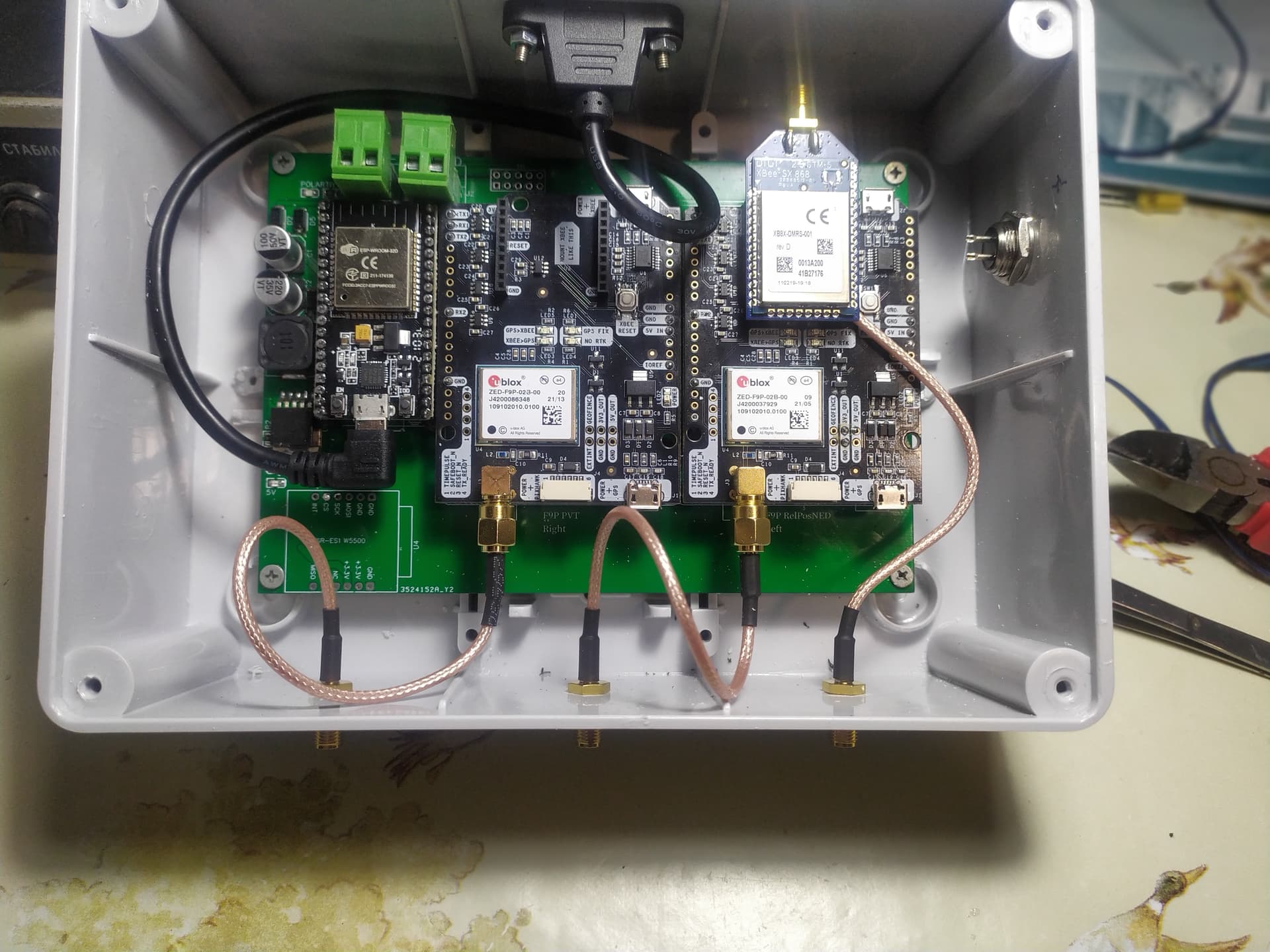
Soldered up another one. I put the ethernet direct like we spoke. It clears the antenna cable better, but still have no access to USB on esp32.
I soldered a header in above the pvt board. The right pin is ground and the one next to it is 5v, to power radio.
Also I moved the ethernet switch over on the autosteer board to be able to make the stack lower. I’ll post pictures when done, on integrated ethernet on pcb
Nice. For the next version we could try to move the w5500 to the right and the esp to the left.
Maybe this would be an option
Or
I’d rather just use a right angle USB cable, I’m afraid the adapter would eventually damage the port in the esp32.
Do you think you can swap the w5500 and the esp23 ?
I want badly to try one with the rtk2blite, but everyone is using the rtk2b.
The problem is that the Rx tx 2 ports are only on the top. So you need at least a cable there. Otherwise it would be really handy.
I could also imagine a PCB which we could stick on top of the rtk2blite boards to connect tx2 and rx2 for rtcm transmission.
Maybe just a breadboard wire.
The sparkfun board is all lower pin. TheGknerd has been using them. I just like the proven durability of ardusimple boards.
I wish we knew if the lite was as dependable. It would make it easier to choose.
Good morning all,
I want to order a PCB on JLCPCB
To have the few elements welded on the left side of the ESP32, is the import of the Gerber Pcb 1.3 zip file sufficient or is it necessary to import another file like the bom? I have never ordered a PCB, can you guide me please?
Hi Don,
You need the Gerber, the BOM and the pick and place files.
On jlcpcb Under the section from the PCB you can select assemble SMT parts. On the next page you need the files mentioned above.
Pretty good instructions here
Thank you Benjamin and Jhmach for your answers.
I did not have time today to resume.
It is especially on JLCPCB that I do not have the method, but I will dig … thank you again
I am thinking about using @Benjamin v1.3 dual GPS PCB, but I also need RS232 out.
Is there anywhere on it where you can pick up the processed NMEA stream to feed into a TTL>RS232 level shifter? 115200 baud is OK. Or is there a better suggestion how to get RS232?
You don’t want to use the almost ready V1.4? There you have a RS232 Out port.
Oh, in that case yes I should wait a little while. Thank you
Are you able to add solder points / pins for the ESP tx/rx pins? And Gnd…that was you can just use a TTL usb adaptor to conncet to ESP for serial monitor / writing firmware, without having to use usb cable / double power it etc…also removes need for getting usb cable in…
I am doing Dual GPS v1.3. I don’t understand a bit on which F9P module you need to install the XBee radio module. I will use a USB connection with ESP32.
If your RTCM corrections are from the XBee it needs to be on the “Right PVT” the position F9P (the one next to to ESP)
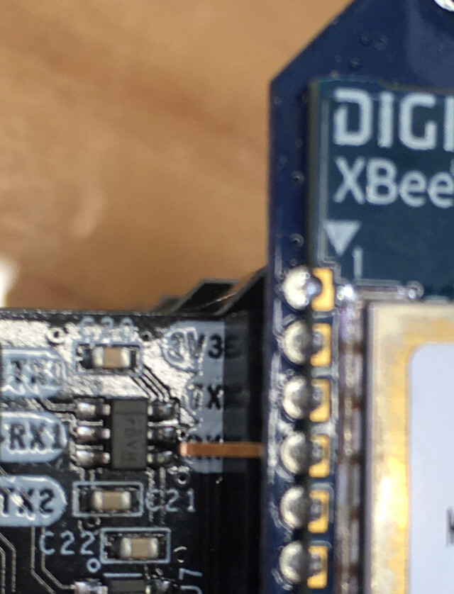
I also bend the XBee RX pin out the side so it can’t get the data that’s getting sent to the heading F9P like this picture
Thanks for the help.
I just noticed. In your photo, the XBee module is shifted by 1 pin. Is that how it should be? I’m sorry. On the module, just the first pin is not used.