Ok, I’m a bit confused now. So let’s start at base one. Do you have 10V on the 2 wires on the planter monitor, or did you get the 10V requirement from the monitor manual?
No I don’t believe that would work. Regulators are very slow and aren’t designed to turn on and off quickly.
Instead, attach the 10v to the collector of the optocoupler with a resistor (10k is my go to), and make the emitter ground. Then every time the optocoupler fires, you’ll get a 10v PWM signal. The only catch is it might be opposite to what you need, but that can be dealt with in software on the esp32 side (invert the PWM rate if needed).
Yes I have 10v coming from the planter monitor. I bought a cheap gps speed pulse generator that I am using now, but the frequency is wrong, and the speed shows half.
Okay, 12v to LM7810. 10v ouput to optocoupler collector via 10k resistor. Zero speed is 10v all the time from what I can tell, so pwm to ground should be correct
So you don’t need a 7810 regulator (the planter monitor already has one). The planter monitor sources the current, and the GPS unit sinks the current. The voltage doesn’t matter, as it is less than 70V. @Torriem isn’t wrong, per se, it would only add some more current for the optocoupler to sink. Here’s how it should look:
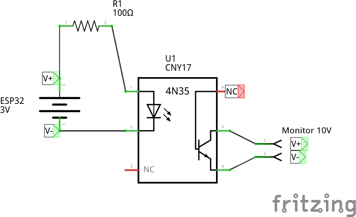
Obviously the 4N35 has an additional base connection, but just ignore that. The rest is the same.
FYI, the planter monitor has an internal circuit identical to what Torriem described.
1 Like
So no resistor in the loop to the planter monitor ?
Edit
Do you have an ETA on getting your code on github ?
I’m using Matthias’ latest for ethernet, and it works perfectly. I would love to just add your speed output to it. I only use wi-fi to change settings via webinterface.
Your planter monitor already has a resistor built in.
The ETA… my schedule is nuts… my code is a mess (it is no longer in sync with mtz8302)… maybe I could just post the relevant bits…
Let me see if my wife allows me to stretch our schedule out a bit.
Ok, at the top of the code you need :
unsigned long prev_PWM_Millis = 0;
byte velocityPWM_Pin = 19;      // Velocity (MPH speed) PWM pin
int velocityPWM_Multiplier = 10; // PWM (MPH * multiplier)
In void setup ()
   pinMode( velocityPWM_Pin, OUTPUT);
   ledcSetup( 0, velocityPWM_Multiplier, 8 );
   ledcAttachPin( velocityPWM_Pin, 0 );
   ledcWrite(0, 128);
In void loop ()
if (millis() - prev_PWM_Millis > 100){
  prev_PWM_Millis = millis();
  double mph_Pwm = float(UBXPVT1[UBXRingCount1].gSpeed) * 0.0022369363;
  // 1 gSpeed = 0.0036 km/h = 0.0022369363 mile/h
  mph_Pwm *= velocityPWM_Multiplier;
  ledcWriteTone(0, mph_Pwm);
}
Beware, continuously updating ledcWriteTone() stalls the PWM generator. I will be on the road tomorrow, but I may occasionally be available. This does not have all the fancy config for setting the PWM in the WebUI, maybe later…
This is great, thanks. I will add it to Matthias’ code and give it a try.
I dont understand how, if it stalls the generator, will it not quit outputting ?
That’s right. High PWM update rate = no PWM = no joy. That’s why the code updates every 100 milliseconds.
Pin 19 is already used for W5500 on Benjamin’s pcb that I am using.

Which other unused pin would be most suitable?
![]()
I plan to just solder a wire for pwm and gnd onto the header for testing
Any pin 32 or less is suitable for output. Except for pins starting in SD. Pin 33 and above is input only. For more info, see ESP32 Pinout Reference: Which GPIO pins should you use? – EmbedGyan Blogs
Thank you. I ordered optocouplers today. I’ll get the code edited and test. May have more questions.
Got the code added to Matthias’ beta, and got it to verify. I used pin 12 of the esp32 since it is unused and next to a ground. Got the 4n35’s in. They are smaller than the 4n33’s on the autosteer pcb, so I cant use the socket. Will just solder direct for testing. Is there any cause to think they will heat if I were to heat shrink them in line like an inline fuse ?
That’s fine. Sorry for the delay, I’m
traveling right now.
Okay, I added the code to Matthias’. I changed to pin 12, and just soldered to the bottom of the PCB, the wires from pin 12 and the ground pin next to it, to the 4N35 optocoupler. Made a mini PCB and used heat shrink to conceal everything but the optocoupler so I could change if needed.
I haven’t gotten it working. I tried turning the optocoupler around, since it doesn’t have a notch for orientation, but still nothing. Could you look at the code and advise please ?
I have pin 12 going trough the resistor, according to the diagram you posted, and the 10v from the john deere monitor going to the middle pin on the output side of the opto.
https://drive.google.com/drive/folders/1l7WvZF7NlAm8rFZtXuqsYysfd3UROIcu?usp=sharing
I don’t see anything wrong in the code. So we need to debug the problem. What happens when you add the code:
Serial.println(mph_Pwm);
right below
ledcWriteTone(0, mph_Pwm);
If you have a current meter, the opto should be pulling around 20mA if you connect it directly to 3.3V using the 100ohm resistor. Maybe a bit more than 20mA maybe less.
Some optoisolators don’t have a notch, they have a groove along the 3.3V input side, or pins 1-3.
Do you have the GND of the monitor hooked up to pin 4 ?
If you have a current meter, the opto should be pulling around 20mA if you connect it directly to 3.3V using the 100ohm resistor. Maybe a bit more than 20mA maybe less.
With no speed, just stationary on output side, yes ?
I do have ground to opto pin 4.
I can add the serial.printIn(mph_Pwm); line and read in the serial monitor ?
If you have a current meter, the opto should be pulling around 20mA if you connect it directly to 3.3V using the 100ohm resistor. Maybe a bit more than 20mA maybe less.
With no speed, just stationary on output side, yes ?
This is to check the LED of the opto. With 20mA current flowing through the LED, the 10V from the monitor should be shorted out. Just hook up the input side (pin 1 & 2) directly to 3.3V with a resistor.
I can add the serial.printIn(mph_Pwm); line and read in the serial monitor ?
Yes. Maybe do this test first…
It works perfectly.
I set the distance calibration in the planter monitor to 1352. It changes faster than AOG, but I figured that is because it is unfiltered. It reads within .1 mph of AOG always.
Great work. Your knowledge of the speed pulse on the Deere monitor was priceless.
Thanks for working out the code.