Most are using Benjamims board with W5500
Does anyone know how I can troubleshoot a wiring issue on a dual f9p plus esp32 stack?
I have built one successfully previously, but I have a definite issue with this one. Tested pins for continuity and all seems OK so I am a bit stumped!
Did it work properly in the past, or was not working at all?
Did you made all configurations on the f9p?
It’s a new setup for another tractor so not had it working yet. Both F9P’s have been configured, I did have rtk fix on both of then, but today when setting up I seem to only be able to get fix on the left one. ESP checked out ok in serial monitor but has since stopped working all together so I feel there must be a wiring issue causing problems!
Has anyone compared the GitHub - Jeep1945/Dualheading: Heading for autonomous driving vs GitHub - mtz8302/AOG_GPS_ESP32: DUAL or SINGLE GPS bridge between AgOpenGPS an GPS receiver. Works with 2 UBlox to calculate heading+roll. Corrects and filters. ESP32 + Arduino MEGA code? Any noticeable difference in steering quality?
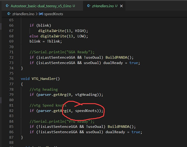
We have the dual code working for the autosteer dual gps pcb, but would like your help getting the speed pulse code added to it. Would you mind taking a look and letting me know what you think ?
https://drive.google.com/drive/folders/1aVtEMrb1iM0aarhk-fQBgG8EhXEfBxBQ?usp=sharing
Thanks
Assuming the speed coming from AOG is KM/H, the ESP32 code translated to Teensy code would be:
unsigned long prev_PWM_Millis = 0;
byte velocityPWM_Pin = 19;      // Velocity (MPH speed) PWM pin
int velocityPWM_Multiplier = 10; // PWM (MPH * multiplier)
In void autosteerLoop ()
if (millis() - prev_PWM_Millis > 100){
  prev_PWM_Millis = millis();
  double pwm = gpsSpeed * 0.0036;
  // 1 gpsSpeed = 0.0036 km/h = 0.0022369363 mile/h
  pwm *= velocityPWM_Multiplier;
  analogWrite(velocityPWM_Pin, pwm);
}
EDIT: This answer is wrong. See the discussion and proper answer below.
I admit I am a bit puzzled. I would think anybody that can write the Teensy code I am modifying should be able to take the Teensy PWM code I supplied and adapt it to their purpose.
Basically, you take the speed input, convert it to the speed output units required (MPH, KMH, knots, etc), times the multiplier (hertz per output unit), and then feed that into the optoisolator using whatever method of PWM your microprocessor supports.
Or am I missing something?
Is this correct?
or should it be:
analogWrite(velocityPWM_Pin, 128); //50% duty cycle
analogWriteFrequency(velocityPWM_Pin, pwm); //pwm frequency
![]()
The second one is right. My apologies, I have a horrible workload right now, and didn’t think this through.
Here is the updated correct answer. Assuming the speed coming from AOG is KM/H, the ESP32 code translated to Teensy code would be:
unsigned long prev_PWM_Millis = 0;
byte velocityPWM_Pin = 19;      // Velocity (MPH speed) PWM pin
int velocityPWM_Multiplier = 10; // PWM (MPH * multiplier)
in void setup ()
analogWrite(velocityPWM_Pin, 128); //50% duty cycle
In void autosteerLoop ()
if (millis() - prev_PWM_Millis > 100){
  prev_PWM_Millis = millis();
  double pwm = gpsSpeed * 0.0036;
  // 1 gpsSpeed = 0.0036 km/h = 0.0022369363 mile/h
  pwm *= velocityPWM_Multiplier;
  analogWriteFrequency(velocityPWM_Pin, pwm); //pwm frequency
}
Maybe next time I need to wait until I have the time to think it through properly.
No worries. Thank you for your help. I will let you know how it goes
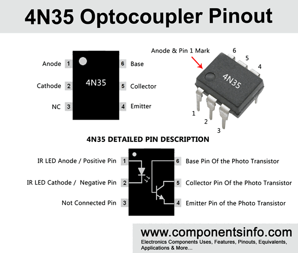
I have half voltage at my Teensy pin, and half voltage on the output of the 4N35, but no speed at the monitor. I have double checked, and the connections are correct. I don’t have a way to check anything else. Do you have any ideas ?
Edit:
Scratch that. Brian and Tony got it working. Thanks
How’s pin 6 connected?
I’ve found unreliable optocoupler operation when pin 6 (transistor base) is left floating.
6 pin ?
Pretty sure it’s just because you can’t use analogWriteFrequency after analogWrite. I also don’t think analogWriteFrequency is made to change on the fly?
Just a simple copy/paste from the standard machine code seems to work just fine. All that uses is the plain old tone function
Yes it is left open. I’ve been using this way for a season, and not noticed any problem.
I didn’t consider the base (pin 6) of the 4N35, but that is correct, it could create unreliable operation. In fact, I use the CNY17: https://www.digikey.com/en/products/detail/lite-on-inc/CNY17F-2/385778
Hello,I have recently ordered some KaupoiMOD v4.1 PCBs and while the material is arriving I am still researching. I have the idea of using two Ardusimple modules - simpleRTK2B:
My question is to connect the two F9P which ESP32 do you recommend to buy?
I can’t find any connection diagram, could you give me more information?
My idea was to make the connection through UDP directly to the switch.
It would be possible to use this Ethernet module instead of the ESP32:
But I don’t know how to configure it correctly, could you help me?

