What can someone tell me about this flow meter? Is this a does H-E mean Hall effect sensor? 5v - red? signal white? Black ground?
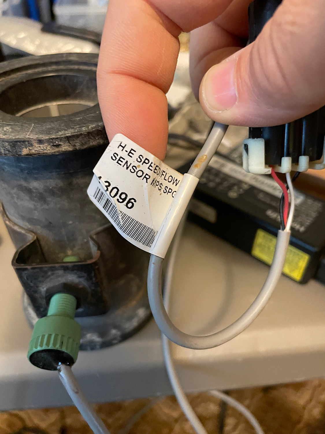
Red is signal
White is 5V
Black is ground
It’s a Hall effect sensor.
Looks like a micro Trak flow meter
1 Like

You can,
I’ve just finished playing with the same valve.
12v will drive it open, swap the polarity and it will drive closed. It stops wherever you disconnect the power and stays there.
Has about a 4 second cycle time.
If you connect it to a cytron you can drive it open and closed with the MA and MB buttons.
Are you planning on using rate control app? Or coding something yourself?
I want to try the rate app. You?
So I bought a new Hall effect sensor. @Hman That link you post doesn’t have the pin out. ![]()
![]() do you have a link that would have that info or are you going off your setup? I want to double, double check……
do you have a link that would have that info or are you going off your setup? I want to double, double check……
Just going off the one I have here.
I only worked it out by trial and error. Don’t think they are sensitive to being connected wrongly, just don’t work if so.
What do i need to test the rate app at home?
A tractor and sprayer. ![]()
1 Like
So I got a new Hall effect sensor as above. I have black to ground. White to 5v. Red to pin 10 (RC15). And I still don’t get any action in the spray app. If I remove the Hall effect sensor and tap pin 10 to 5v I immediately see flow in the rate app. Any ideas?
Is there settings that need to be changed to recognize the Hall effect sensors signal?
The highest voltage I have seen on the signal wire is 2.5v. Is there a voltage divider I should be by passing for that low a signal voltage?
You could be right. Try using a smaller resistor, maybe 800 ohm between pin 1 of R2 and pin 1 of U1.
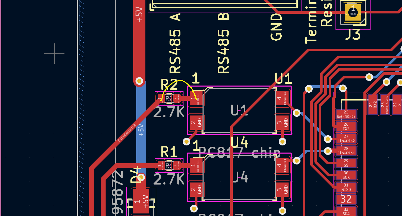
Sorry that was the wrong opto. It should be pin 1 of R1 and pin 1 of U4.
Ya that would probably be a better solution.

Set this up before your reply and Viola!!!
Just some wrapping wire direct.
That works too!
Next board will have have a switch for 5v and 2.5v signal ![]()
![]()
![]()
![]()
1 Like
They are 12 volt flow meters, given the opto, is there any reason not to provide 12 volts to it rather than only 5?
My spray controller just uses the internal pull up resistor and the flow meter straight to the pin, no opto so I am limited to 5 volts. You may not be?
Oh? I didn’t realize for some reason I can’t find any data online and someone posted on here that white wire was 5v so that’s what I tried.
@SK21 just trying to understand the rate app better maybe this is somewhere in the help and didn’t find it.
I’m a newbie to spraying. I am expecting the rate app to restrict the main valve by the ground speed and amount of length of section currently applying. Is that correct?
One time I noticed a message saying my section sizes had changed. Does the app”watch” agopen sections?
Does-
*standard valve output -12v to +12v (my valve uses + to open and - to close)?? Is this the correct setting for my valve?
*combo??
*motor output 0-12v?
I calibrated my flow meter by running it into a bucket to get the pulses per litre. I thought the calibration function was to set the limiter valve is this correct or is it to setup the litre per pulse.
Yes it varies the main valve based on ground speed and working width.
AOG sends out a pgn when the section sizes change. The rate app reads the pgn and adjusts the section sizes in the app.
Standard valve outputs -12V to 12V when using a cytron. The combo does the same, but also closes the valve when the master switch is off. Motor control does output 0-12V.
1 Like