Grade control

You will have to edit the .agd file and add a first line with this:
Latitude (deg), Longitude (deg), Elevation Existing(m), Elevation Proposed(m), CutFill(m), Code, Comments

I tested your .agd and it seam to work, if you don’t add the first line it will skip the beanchmark.
I don’t remember exactly now OG3D read the file, it just skip the first line, another thing to improve.

2 Likes

I just downloaded Visual Studio and am trying to learn the OpenGrade3D, but that is going to take time for me… I do understand the arduino code, am I understanding it correct that OG sends a value from 0-255? I am wanting to change the code around a little bit to set it up to input directly into the tractor… What Im understanding is >100 is down and <100 is up, is this correct?

It gives the distance from target in millimetre, 100 on target.
Greater than 100 mean the blade is above target so must lower.

You cannot use the value directly as pwm, there is a lag between GPS reading and the value sent to the valve.
The calculations in the last .ino works pretty well, you should use it as a base.

Should be easy to convert to “danfoss” valve.
Divide pwmValue by 2 and add 128?

Thank you for explaining that it sends a value in mm… you will have to explain the delay a little more… while I know there is always delay, are you talking about the delay between obtaining location and action of valve? Or are you talking about the delay between telling valve down and the physical act?

I know deere uses a “look ahead” basically it takes mechanical delay of a planter or sprayer out.

One or both need to be written into opengrade, because the arduino only knows what to do, not what’s coming up.

Do you have a tractor with CAN valves? If so, you can use my ino directly from here:

You can just put it in between the wiring harness to your hydraulic valves, it acts as a CAN bridge so it sends all the traffic through except for the valve which you use for blade control, just adjust the CAN IDs as needed.

It uses the valve float mode to put the blade into automatic control from OpenGrade3D, you can manually run the blade with the tractor lever and just flip it back to float for auto mode.

2 Likes

I originally was going to look into can, but there is a simpler way… all deere, cnh, and cat tractors made in the last 15 years come with a scraper interface… basically you plug and play. DAC 8000 Wired - Manuals

Not sure of the wiring for cnh or cat but here is the configuration of deere

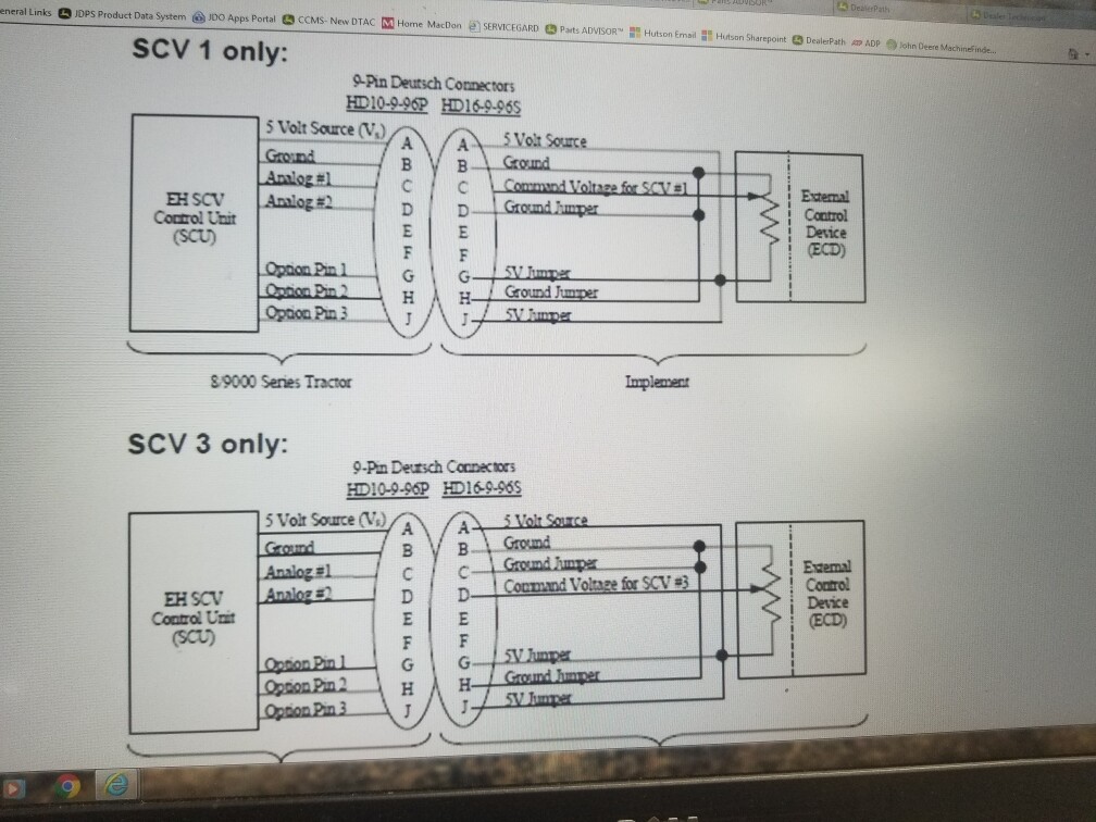
It is a 5v analog input that doesn’t like extremes. So 0-2.5v controls one direction and 2.5-5 controls another…
CNH and JD have a dead band from ~2.25 – 2.75 volts, this varies some from tractor to tractor.

CNH and JD will through error codes if the voltage sent < .5 or > 4.5.

3 Likes

Should work like the Danfoss PVEA for autosteer then, take a look at the v5 ino and copy paste from there the relevant parts.

Still, if you have CAN valves it’s dead easy, just find a connector in the hydraulic bus where you can plug in between the controls and the valves and use Teensy triple can board, zero soldering and less than 100 bucks.

2 Likes

How does this interface to tell it to lift or lower? I just reread your post, so it looks like if we add certain voltage to that selected pin it will go up or down? As long as that voltage is applied it will lift or lower and then when we take the voltage away it stops?

1 Like

Close… it has to be fed a voltage from 0-5 all the time it’s connected or it will throw an error code.

Basically .5 - 2.25 controls a direction, and 2.75- 4.5 controls another

Staying away from 0 and 5 keeps the machine happy and the dead band 2.25-2.75 is for zero movement

One of these days I plan on learning can-bus but for now I just want to get the blade moving and I already have the arduino set up for the tractor… I was planning on using ezigrade to dump out values to the arduino and I might still… just exploring both options

1 Like

So no blade movement send it 2.5 volts, then something like 1.5 and 3.5 to move it up and down, the bigger the swing do the hydraulics move faster?

1 Like

You got it… Its alwayd trying to get back to neutral (2.5)… the further away the more it will open the valve to try to return.

1 Like

So you could do this with a Cytron and send voltage like a rate controller, just vary the voltage like a motor with 2.5 volts being the neutral position?

1 Like

It’s sometimes tricky, for example if the cytron’s PWM input gets turned off, then your output goes to 0v. I think better would be to create a 2.5v reference and then use the Cytron to pull that up or down to control the valve. Then if something happens with the Cytron then at least the valve goes to neutral.

2 Likes

I did not use a Cytron, I ended up with a nano tied to a mcp4725 (i2c dac) and a LM358 op amp to use as a buffer to make sure I didn’t overload the dac.

Technically I could have just used the opamp on a pwm pin of the nano, but I wanted a true dac to send signal to the tractor.

I hook both ground and 5 volts to the machine. This keeps the arduino running as long as the tractor has power, and with a watchdog timer that defaults to 2.5 volts after a second if the arduino doesn’t get new information.

A short video using random data in the target,actual,/n format for ezigrade.
https://youtube.com/shorts/pHxKV5jln5k?feature=share

I plan on working on the code for opengrade this week while it’s raining

2 Likes

Very interesting, I had to Google a few parts in your diagram but mostly makes sense now. So the nano holds the code to tell what voltage to give out, it gives that voltage signal out digitally to the 4725 which converts that from a digital signal to an analog signal. That voltage then travels through the LM358 where it is boosted? By boosting does that mean same voltage just more amps or power?

Couple of followups,
1 If we supply voltage at this point to tractor does it back feed or cause any issues to tractor switches in cab or on the Can?

2 To make this work do we need to put the hydraulics in float on handle in cab? Or can the cab hydraulics be used at same time as this for manual overide? Would we need to switch this on and off to use cab switches?
Does the timer setting for flow time in cab affect this at all?

  1. If you vary the swing of voltage does that increase the speed of the hydraulics flow. For example does 1 volt flow faster than 2 volts?

This is very interesting, sorry for so many questions

1 Like

Cool feature on the JD! Only if they’d provide a digital control as well…

ISObus standard should allow for controlling valves via the Isobus gateway, but currently don’t know of any machine that would support it, so you have to do it the dirty way by hooking into the hydraulics can directly.

1 Like

Ill try to answer the questions to the best of my ability.
the nano receives the information (from opengrade >100 or <100) to determine direction up or down… the arduino takes the distance from 100 and sends out a pwm signal thats related… as an example if +100 is up and +2.5v is up(assuming) and the deadband is 2.75v then 101 → 2.75v, 120 → 3.5v, 200 ->4.5v (these numbers are all made up to show the interaction)

The greater the voltage the more hydraulics are applied, in much the same way if you just barely touch the lever it will be slow and the more you push it increases up to the flow rate.
The limits (.5v and 4.5v) represent the extremes of the flow rate, which you set in the monitor.

So, the nano sends the pwm signal via I2C connection to the 4725 which is a 12bit DAC (digital to analog converter), the output of that goes to the lm358 as a booster. Basically the only reason I did this was to use the tractors 5v power to supply the energy to send the signal through 3 ft of wire. I was not sure how much amperage was needed, so I took the weight off of the DAC.

Once hooked up, which has to be done with the engine off or it throws codes, the tractor recognizes touchset control is hooked up. The SCV acts normal and can be used in any way until you do a forwared detent. At which point it reads the signal and controls accordingly. One note, on the 9R I tried forward motion is also needed, I can only assume for safety reasons.

There should be no backfeed as this setup was engineered by deere themselves, its basically like feeding information to a nano on a pin to do another operation.

Timer is no existent, only flow rate.

Nut,
Im guessing the reason its not digital is this was designed more for a potentiometer to control depth of tillage machines… and like most Deere things it worked so they decided to run with it for other things (igrade, scraper, etc)… Watching the new scrapers Im guessing iso is used, or will be shortly… Im sure it could be used now but it would take someone smarter than I am at ISO.

Hope this clears up the mud a little bit.

Will this work the same on a Case 4wd tractor? I can’t afford the green ones :grin:

I know case uses the exact same 5v method as long as it’s drive by wire…

DAC 8000 Wired - Manuals has information on where to look, and you will have to get information from your case dealer on how to wire it up.

Well, it’s not really a question of look ahead… it’s more about integral and derivative.

The GPS gives a position only 10 times a second plus some millisecond to do all the calculations, send it to the arduino, do the calculations, send to the valve, make the spool actually move…

So if you only make the valve move according to the offset distance this will happen:
It will just overshot continually over the target because as soon you will have a big correction it will move fast to the line and by the time the spool is at the right spot, after the GPS read it was on target, the blade would already be way over.

@ChrisC thanks for the info for JD SCV control, I will be able to compare directly OpenGrade3D to the Trimble Grading software, on a 450hp 4wd with a 20ft blade! :wink:

1 Like