To test they are all currently on a bread board…
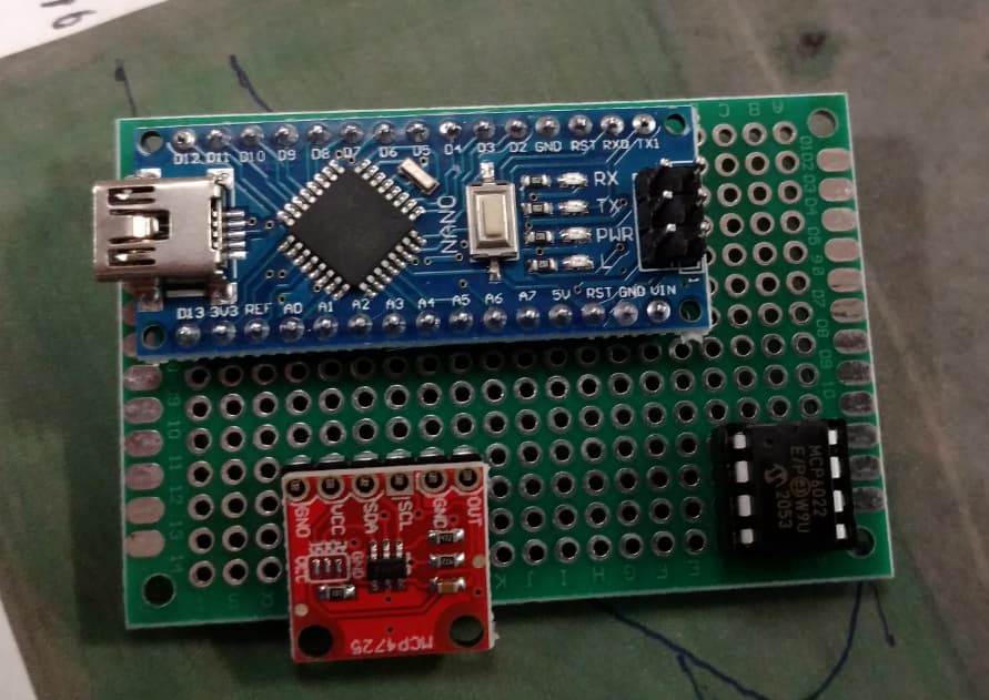
I do have perf board that I am going to use for now since I haven’t designed a pcb… thats on the todo list
To test they are all currently on a bread board…
I do have perf board that I am going to use for now since I haven’t designed a pcb… thats on the todo list
Is their some way we could use a nano 33 IOT for this and go wireless?
Could go with wifi or bluetooth module as well? Wireless antenna is on my todo list to get rid of the thin antenna cable dangling in the dirt…
Have to look at the 4725 data sheet… the nano your talking about is 3.3v logic, not sure of the 4725 off hand… be careful with 5v around a 3.3v board
But having a quick glance at serial over Bluetooth protocol it seems pretty straight forward as a com port…
I may have to look into one of these with 5v logic to go bluetooth
My experience with the Nano 33 is that it is not reliable. The wifi looses connection.
I think ive got the parts i need now. A variety of PERF boards (never used these before) NANO, mcp6022 with a mounting socket, MCP4725 breakout module.
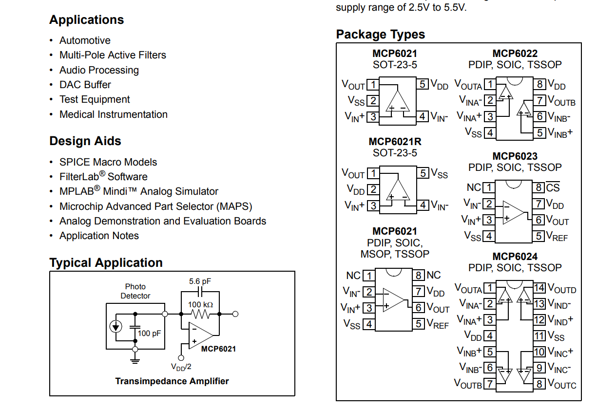
Watch the pinout of the 6022… not sure if it’s the same
Look at the plus and minus of the data sheet that hookup will be the same
was hoping for more detailed shematic before i start soldering. Not sure if i understand how the 6022 is hooked up.
VoutA will be your output to machine as well as tied to VinA -
VinA+ will be tied to output of 4725
Vdd is 5v input.
Vss is ground.
A 6022 has two opamps in the chip, will use the other side when we go to impliment lateral tilt/second scv
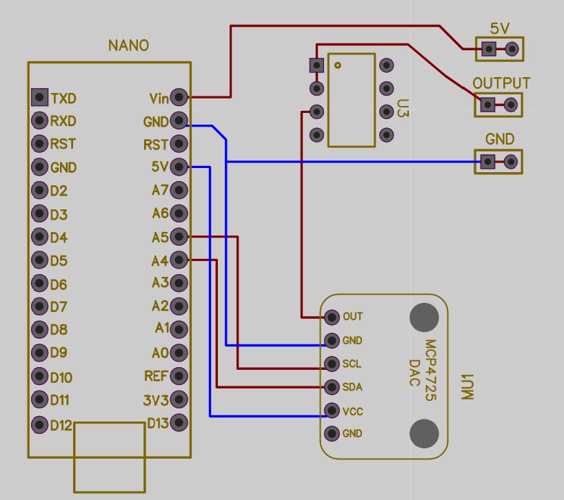
Here is a quick pcb design… I plan on making some changes (double dac/opamp) for controlling 2 valves. but this will get you started.
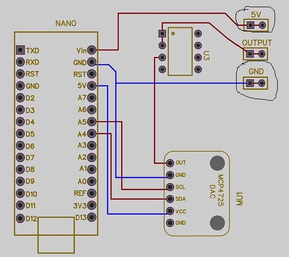
So the 5V and GND are connected to the machines 5V and GND. Correct?
Yep… make sure you tie the machine 5v to VIN…
this will make sure the power gets regulated, shouldn’t be an issue but its a safety measure.
So do i need to hook these up your schematic doesnt show it?
Good thing I didn’t get one made up yet.
Yes those need to be hooked up.
if i feed 5V into vin on nano. Should i have 5v at the 5v on nano? Im getting 3.82 right now
yeah Vin is for 6v or more it goes trough a regulator.
You should connect all 5V to the 5V pin.
So 5V from machine should go to 5V on nano not VIN?
Run it to 5v… or you can leave it off if you are powering through usb connection… just make sure everything is grounded to reduce the chance of grounding potential.
I would double check your 5v source, if it’s stable then you can put it on the 5v rail
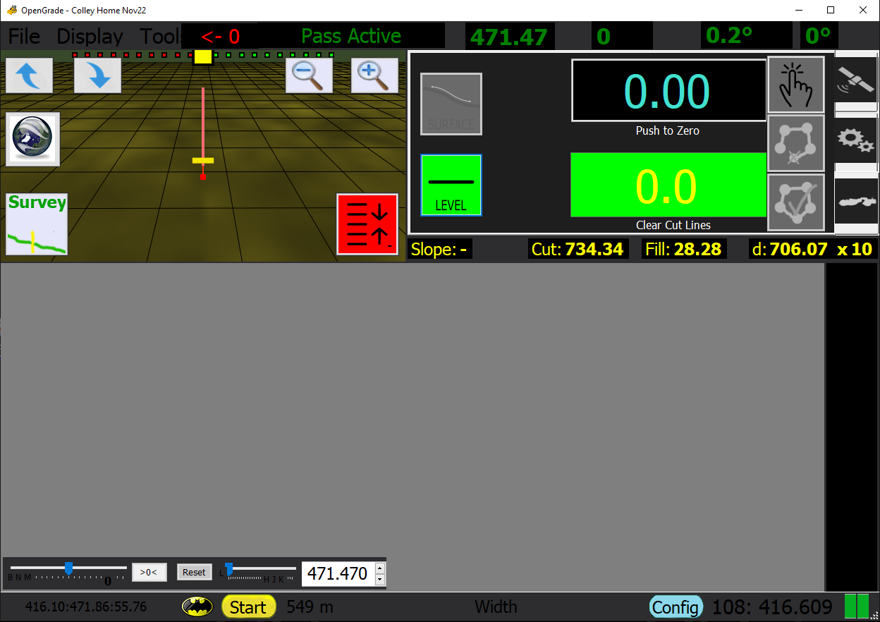
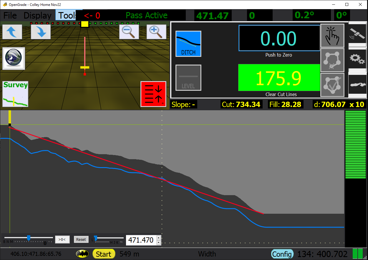
Hey Guys, wish I would have found this forum before I began working on my revision of the open grade program, it would have saved me a bit of time as many of the things I implemented have already been accomplished by members of this group! Live and learn! Anyways here is a few screen shots of what I have come up with. Seems to work generally on the same principle as the others with serial COM to a Microcontroller for automatic control. Biggest difference I can see is my use of modes; Ditching, Surface, and Tile. Currently I am working on an algorithm for automatic cut line creation, as I have seen it mentioned a couple times above. I didn’t see that someone had come up with the solution. If it has been created let me know so I can Focus my efforts on other features Users may like. V3.0.1_Ditch|690x486
