The Cartesian coordinates of a point in three dimensions are a triplet of numbers (x,y,z) . The three numbers, or coordinates, specify the signed distance from the origin along the x, y, and z-axes, respectively.
It’s my limited understanding that the ublox GNSS will do this, so the code will need to control all three axes to grade property, grade a road, dig a dam . If the Z reference could be millimeter accurate it would make this board very powerful
So maybe that how the very expensive modules make it work.
Use three antennas
Antenna one, for auto steer
Antenna 2, for left blade
Antenna 3 for right blade
Maybe using 2 boards
This type of reference opens up the potential for automated fence installation and or plotting a property robotic farming
Ok
this is how opengrade work then.
It look for his x and y position then gives you the actual z position and the vertical distance to the target height.
The ino code(arduino) make then move the blade to reach the target.
With RTK F9P the theorical precision is about ± 15mm. In real life the pass to pass height where maximum 7mm off sometimes(heavy clouds) with the base 6 km away.
Most off time I could not see an height difference from pass to pass.
It works, I’ve run both simultaneously no problem. Would be more convenient with two screens. For surveying I used a serial port splitter to log the data with OG3D while doing something else with AOG.
As for accurancy, similar experiences. Levelled one field 17 km away from base with no problems. Based on my experience OG3D + OptiSurface combo doesn’t lose on any area to the 20-30 keur Trimble etc. systems, except being so cheap that you don’t get the street credibility and reputation for a thick wallet ![]()
6 Likes
If anyone needs it I got the danfoss valve setup going, my use is to input the value to a deere tractor, but it should be the same for cnh and some cat machines.
The ino is rough right now, but I plan on cleaning it up this winter.
This is not can bus. For deere it’s called touchset.
Hookups can be found here DAC 8000 Wired - Manuals
Ino found here
3 Likes
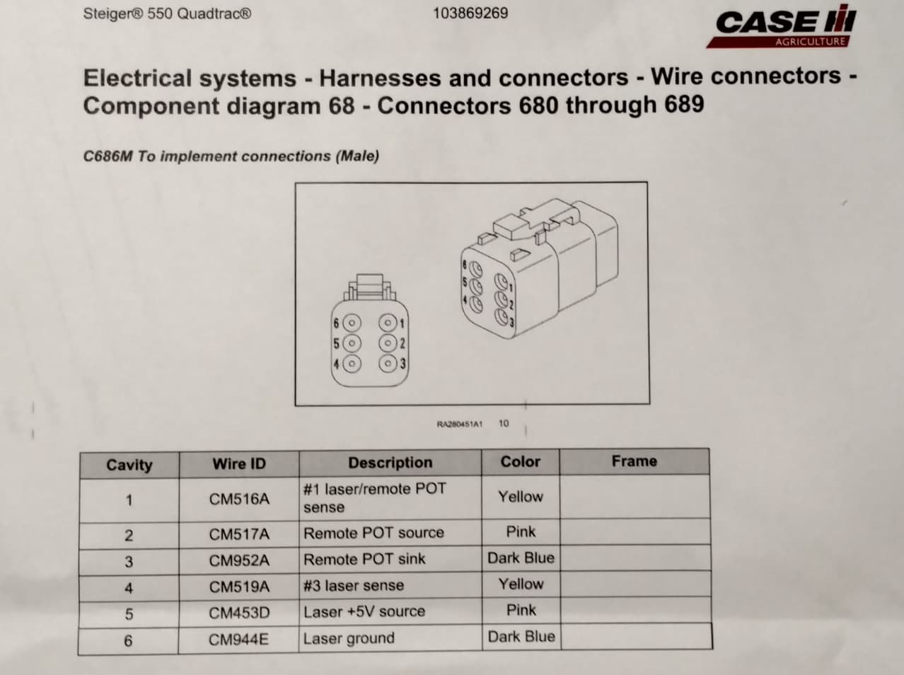
So ive got a quadtrac 550. Was getting set up to run an external valve for a scraper. But looks like i could just use an scv with this? Will this work with standerd open grade or just 3D? Would appreciate an more detailed schematic. ![]()
OpenGrade and OpenGrade3D work the same manner. So the inos should always work on both.
I’m also interested in the schematics.
It use this Adafruit MCP 4725?
Yeah it uses the mcp4725 as an external dac. Currently im using a lm358 as an opamp, but that is getting ready to change… as I have been learning it is not a rail to rail opamp since I cannot get full 4.5 volts out of the high side.
Currently waiting on a MCP6022 which is a rail to rail.

Haven’t made a gerber file yet, but I am going to put a perfboard pcb together.
As far as how to hook it up on case you need to call your dealer and find someone that can look up the pinout for a scraper control for case.
As far as using the ino it is setup to take in the 1-199 from pat’s opengrade3d. Not sure if it works the same in the original.
So are you powering the nano , 4725 and the op amp from 5 volts pulled from the deeres plug?
it looks like my quad has the plug in the DAC manual. can these plugs control all the scv’s or just a certain one?
I do have 5 volts coming from the tractor and it’s tied to the computer 5v as well…
Two reason is 1. I want the arduino to start with the tractor so it doesn’t throw a code, the arduino with no Input from computer will default to 2.5v which is neutral.
- I want to make sure it did have enough current, should be an issue but I didn’t want to overcurrent the controller.
So the 5v goes to the 4725 and the opamp.
1 Like
Am I reading it correct that you can control #1 and #3 valves?
What has to be hooked up to make it work, or do you setup in the cab.
On the deere one pins have to be pulled low or high to make the system work.
1 Like
Havnt compared to your deere schematic very close yet. To me it looks like 1 and 3 SCV are controlled. The SD drain manual you posted a link to tells how to go in and change settings on the quadtrac to activate the scraper control. So would the Laser sense be were i feed the .5 - 4.5 volts into. Please give your thoughts on how this compares to Deeres plug that you are working with. If i understand right you dont have to configure your tractor it just senses that you have something hooked up and reconfigures automatically
Just looking at the plug schematic it looks like there are two “types” of controls. Remote pot and laser.
If I understand correctly deere touchset is technically a remote pot setup… meaning it’s for a potentiometer sitting out on an impliment. But the thing is it doesn’t care how it gets its voltage.
What I’m slightly confused on is the remote pot source, sink and laser 5v ground… pot source sink should be the same 5v and ground, no idea why they pinned it out twice if it’s configured in the cab.
So the .5 → 4.5v are configured in OG3D. I will have to post values that are represented for the pwm values, I really should put them in the comments of the ino.
For deere it’s configured for laser automatically. If the plug on the tractor is not plugged into anything it defaults to standard… when you plug in you tie some pins high and some low with a voltage on one… that sets the machine to auto control. You have to plug into the tractor with the machine OFF… if you don’t it throws codes that have to be removed before automatic operation can resume.
2 Likes
It looks like you config the tractor and than activate automatic control with the 1-3 button on armrest.
So the way it looks to me all i really need to do is pull +5v from pin 5 gnd from pin 6 and then let the nano/4725/ and op amp feed the varied voltage back through pin 1 to control SCV #1. When my parts come in ill get a board based off your info put togethor. Really excited about this if it works it will give much better control than my small external valves
1 Like
Report back… if you had an opamp and it was hard to get the dac you could modify the code to output a pwm on a nano pin and then run it through an rc low pass filter.
That’s how I started learning.
I’m going to get schematics together and put them on the github…
1 Like
i should have the parts youve talked about on the way
1 Like
It will be fine but I did order a different opamp…
Mcp6022 is true rail to rail vs the lm358 which is not.
Basically this means the 358 will not reach the full 4.5v whereas the 6022 should… I haven’t tested yet.
The way deere works is .5->2.5 is down and 2.5-> 4.5 is down… so you will just not have a full down with the 358… not sure if it will matter… to wet to test here
1 Like
i actually have some of both coming. But not sure how you are assemblying all the parts without a PCB?