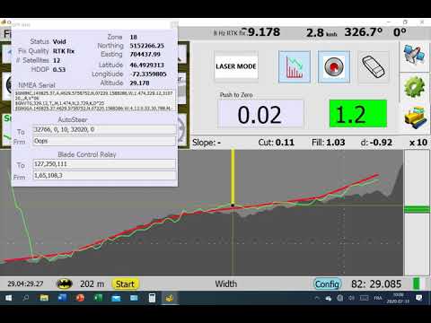
@kansasfarmer I am going to mount a prop valve on my blade, I wasn’t satisfied with my bang-bang valve.
I will use a Hydraforce SP10-58C prop with a M+S Hydraulic PRTA40 priority valve.

This is great! Right now this is way to advanced for my coding skills but I will take a look at it and make a survey. How much points/Ha/meters you think we can drive before there are to much points?
Yes mines burned out after 8 hours of levelling.
I talked with a guy who does leveling for a living and he recommended 10-15 meter between passes when surveying. If we ha 1 hz saving and say 12 kph speed, that would be 3000 points / ha. I’ll try to do a test by creating a field of some tens of ha to see how it works. The optisurface guys recommended exporting in a 5 meter grid so that would be 4000 p/ha.
The python code will manage that for sure, don’t know if there’s trouble elsewhere.
For the visualization, I try to make a line in the heading direction and draw the profile along that, now it’s bit messed up to read as you jump from a line to another.
Another thing to add could be some kind of max cut limiter or a nudge upwards if the blade goes too deep.
Okay, some updates again. Tested making a 100 hectare field, i.e. 1 km x 1 km with 5 meter resolution, so in total 40 000 points with some made up profile, just a constant slope.

It’s now creating the Contour.txt file completely from scratch, also can do the coordinate transform from lon/lat to UTM quite easily, so with small edits to the script should be easy to use all sorts of survey data. Maybe could aid in visualization if it was just the map mode with colour for the altitude. @BrianTee_Admin maybe knows how easy/feasible it would be just to render it as a surface from the point values, I’ve no experience with the graphics side of things…
@nut Can you give the meaning of each point value in the contour.txt file?
ex: 0.698,0.004,28.968,100.01,53.4365372,-111.260047,99.9999502,100.005,0.2
easting?, heading?, northing?, altitude, ?, ? , height of the red line(-1 when none), height of green line(-1 when none), dist from previous point? or speed?(0 for first and 2th, -1 for last)
red line is the target cut height
green line is the recorded line (when pressing the rec button)
You mean max cut per pass?
We could probably code something in opengrade to record the green line when it goes deeper than the field height(4th value) or his previous value and use the green line value to set the max deep for this pass. Or just use this green line value to show the “work in progress” in a 3d view.
Yes, that was the idea that one could limit so that it doesn’t try to cut something like 30 cm at a time. I think some of the commercial stuff has like a nudge button so you can temporarily add 5-10 cm to the blade height as long as the button is down.
As I understand it goes like this:
$Offsets
offset_easting, offset_northing, UTM zone
number_of_points
easting-offset_easting, heading, northing-offset_northing, altitude, latitude, longitude, cut_altitude, last_pass_altitude, distance
easting-offset_easting, heading, northing-offset_northing, altitude, latitude, longitude, cut_altitude, last_pass_altitude, distance
…
The offsets are there probably to keep the precision as the integer part is a very large number. The UTM zone is needed to do the conversion correctly to lon/lat. So the actual easting/northing values are the offset plus the value in the list. The last “distance” item I don’t know what it’s used for, same goes for the heading.
what is the priority valve for kindave its own load sense circuit? is the way you have it drawn goin to circulate oil through scv even when valve is not operating?
thanks
hi,
Yes the M+S Hydraulic PRTA40 priority valve will send only the amount of oil needed to the prop valve. When the prop valve is in neutral all the oil will go back trough the EF port with minimal pressure raise.
My Valtra have a gear pump and use a danfoss OLS priority valve for steering and all the excess flow goes to the working hydraulics.
I have now all the parts, I should be able to test it next week.
Would you mind telling a bit about the OptiSurface application? Did I understand correct that you are using a trial version? Are you planning to use a licenced copy if all goes well? How is the trial copy restricted, time limited or feature limited or something else?
I feel the planning tool being an essential part of field levelling but haven’t seen any open source applications. OptiSurface I happened to see “live” at our neighbour’s field. Or I only saw the tractor working on the field where planning was done with OptiSurface and the driver was quite happy with the app capabilities.
hi
I am interrested to. I didn’t fund any trial version. From what I saw it will cost 1000$Us for 300 ac?
Everybody around me is using OptiSurface, it seem to be the most popular, are there others?
Also, I mounted my prop valve on my blade.
The first test was not as good as I expected! The cut was wavy and the blade overshooting continuously.
It appear that there is a great delay from the real elevation measurement and the display/valve command. I think something like 0.2-0.3 second.
So reacting only on the distance from the cut line don’t work. the time the arduino think it reach the line it already overshot.
So my new arduino calculate the pwm value 10 times/sec and take in account the 3 last values to calculate the value.
Maybe it’s some PID? ![]()
Now it works great:
The last versions are on Github, on development! This arduino is in the beta branch right now.
As for optisurface, there’s no trial available. I also tried out Trimble WM Form, but it’s way less features and they never bothered returning with pricing to me. Optisurface did one field design for free for me as a demo so based my purchase on that plus experience from one contractor using it. So far been testing it on one field with different designs. The cost is like Pat said $1000 for the software which includes 130 hectares worth of credits for 3D design. The additional credits are around $7/ha. Just email their support if you have data handy. The demo field I did ended up with around 130 m3/ha with opti, couldn’t push under 200 m3/ha with Trimble. So did a bit of blind purchase. Thought about DIY and played around with the elevation data in python but fitting something more complex than a plane or a polynomial surface needs a lot of work, so decided to buy to software this time.
@Pat looking good! I guess it’s sort of integral term? One could think of sine kind of look ahead functionality as well like in steering?
My blade is still on it’s way from Italy so some time until I can do some testing. Also some harvesting to do in between ![]()
Hi. Ive been lurking in the background and watching progress on this with lots of interest! Regarding optisurface another alternative is Ezigrade
Our neighbours use this for their lamdform designs in conjunction with aguide software.
From memory they paid ~$1500AUD for the full version of this software.
what kind of software do they use it in conjuction with
Now it makes only short pulse when near the line, you can see it in the video (2nd value frm Blade Control Relay)
I will make some tests, but I think on-off valve can make a decent job now.
With this arduino code min and max pwm will be set at 255, gain not used(no effect). It’s the IntegralMultiplier (now renamed OverShoot reduction) who will determine the length of the pulsations (to set between 20 and 40). Deadband around 5, it’s the dist in mm from the line the arduino will make no corrections.
This as to be made with a cytron or similar, relays will burn to way to fast.
So my dozer is a 24 v. I have a valve now that i can add to the hydraulic system which is a closed center pressure and flow compensated. If i understand you right. I could run this on/off valve with a cytron instead of relays? It has 24 volt coils is their any problem with that?
Thanks
The cytron MD13S is rated 6 to 30V
I am now wired like this, only power from usb:

I think it will also work with a PCB with only a arduino and cytron installed.
I levelled sand for a 40x120 ft slab today, all in full auto, it made a great job, I will test more in September with a 3ac field to level.
Are you already able to export a levelling map from optisurface back to opengrade?
What are the possible output formats?
I am looking in buying the software.
I will also try to learn this Python stuff!
We will level most of ours field in the nexts years since we have an uncle who owns a JD9520 with a 20 ft blade and Trimble GPS. Currently he has his maps made externally, all with Optisuface.
If we can make it work I will be able to level with my 14ft blade.
I looked a little bit at his screen while they were levelling and it seem to be really basic for the price it cost!
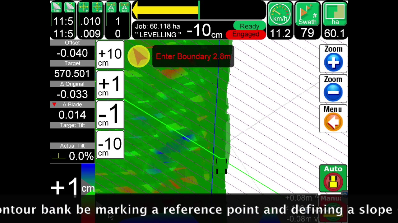
The GUI was only a map with colours depending the cut/fill and was no changing while cutting. Maybe this is doable in opengrade?
A bit back I was working on some variable rate stuff. I was able to control the color of the applied area with a scroll bar. All this did was give the third term in each section a value between 0 and 255. Then a given color was set to draw the sections, say red, at that color. Gave a nice display, Saying that, could not AOG map the elevations with the color just the same. Could not each gps fix be applied a color to be seen in the map. If two colors were chosen, you could display a large range of elevations. Just thinking out loud.
@Pat the output formats are shapefile, agps file (which is basically a text file with lon/lat/original elevation/proposed elevtaion/cutfill values) and some trimble .gps binary format. It now works to import back with the agps file (need to do some work on parsing it properly still), only stupid thing is one needs to convert back from easting/northing to lon/lat. So I’m now looking into the shapefile, which should be XY data to start with. But it should be doable both ways, just worried about losing accuracy in the coordinate transforms, but maybe that’s not an issue.
As for hardware, I’ll solder together one extra PCB (kaupoimod2) that I have around, basically just to hold the cytron in place + the power relay so I can drive the valve through the PCB power. I guess one can drop the 5 volt stuff, unless it would make sense to put in the AD converter as future option for draft control…
@KentStuff good idea, need to take a look at the applied area drawing code! I’ve been struggling bit with the opengl bit, hopefully some time to work on that this week.
We did the reverse conversion, thanks to Brian it was already in the code. With a bit of fine tuning and Brian sending me back to “the school of the obvious”, precision was spot on. It is now part of the main code in the kml writer. Here is the link to the original question:
Also search for background and section to kml in the forum.

