Hillside combine installation and the BNO080 IMU

Hi all!
Been away for a while but starting to ease myself back in to the scene :slight_smile:
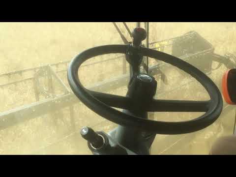
Thought I’d share a few photos and notes of my install on a Claas Lexion 630 Montana. While I’m sure these notes will apply to most Lexions, of course your mileage may vary.

I am using a Miran WY-01 linear sensor for steer sensing. This is uncompensated for Ackermann, which doesn’t cause a huge problem but it would be nice to fix it in software one day. The sensor is mounted to the ram with a 60mm exhaust clamp and a 25mm pipe clamp.

The valve is an old one, an Atos 4 way proportional piped directly in to the main block. This combine does have load sensing, however an assumption I can make is that when harvesting, the system will always be at full pressure due to the chaff spreader and reel hydraulic motors. This saves a lot of bother!

It’s handy that the steering lines are tee’d in a convenient location from the factory, directly above the block. When connecting to the main block, I chose to use the plugged ports on the very bottom. I had real trouble finding matching connectors, however after some digging it turns out they are ISO 6149. When opening the block be prepared for a heavy flow from the T port! Disconnect the main return pipe at the hydraulic tank in the engine bay to prevent siphoning.

The wiring was brought into the cab through a gland into the main electrical box. I was concerned about noise on the analog steer signal, however looking at it on the scope it’s remarkably clean. An update will be to place an ADC on the rear axle and then implement a OneWire bus back to the cab. (So I can use the existing wiring and because it is a very robust protocol)

In the cab I am using a Chuwi Ubook Pro. This 12.3 inch tablet is actually very capable and well built, and the fanless design is ideal, and it charges on 12v. Connection over USB to the arduino, Ardusimple RTK2B Lite and a Sierra MC7700 modem.

I am using a single antenna with BNO080 IMU for heading and roll. It’s the same silicon as the maligned BNO055, but with much improved software from Hillcrest, so it is rock stable. I thought I might be able to get away without an IMU because of self levelling, however this only ends up in a fight between the autosteer and the levelling, and one seasick operator. The levelling does not cause offset issues as the wheels themselves are raised/lowered, preserving the centerline of the machine.

The arduino is running my custom .ino, and because I haven’t ported it to the new version, I am still running AOG v309. The main features are button on/off for autosteer and the BNO080 code. I take quaternions from the chip over I2C and convert them to yaw and roll angles, then massage them to the correct format for AOG. I have disabled the kalman filter because the BNO080 is very well filtered already. See my other thread on the pinmapping of the combine handle for discussion of taming the combine’s signal to arduino-friendly signals.

My photos are too large to fit on this forum so have a google album instead: https://photos.app.goo.gl/Rz9PUYwR7wX2pDU16

Hope someone finds this helpful!

14 Likes

Do you think your valve is about the right size? If I’m reading the pdf correctly, about 28 L/min max. What’s your max PWM set at?

Yes it seems about right, maybe a little too big. There was no real design process behind it, it’s just the valve I had to hand.
Max PWM is 100% but it never gets that far, Min PWM is 55%

Is that the Sparkfun 080? Are you also using their library? I have one, just can’t seem to find the time to hook it up.

Yeah this is using the Sparkfun 080, although I have the AliExpress generic modules on other machines which work just as well.
Just using the Sparkfun library and some quaternion maths to extract yaw and roll.
Thrown it up on github for you to look at.

1 Like

Thanks for sharing Charles that looks brilliant! It was your earlier posts on the combine forum that inspired me to make a base station and experiment with hydraulic valves.

I’ve been putting together a system for a 430 Lexion (1997 green chassis). I have made a similar hydraulic circuit to the analogue AutoPilot system of the time using a check valve, accumulator and pressure switch to ensure pressure behind the control valve. Good to know you have not needed this on your newer machine. The valve is a hydroforce SP10-47C and I am using a Honeywell RTY90 rotary sensor for the wheel angle sensor. For the autosteer on/off button I’ve made use of the trigger on the control lever which is for moving a Vario header in and out but is redundant on this machine which has a fixed C540 header.

I’m using Brian’s PCB V2 and mtz8302 dual antenna gps both are working great without any problems. I have these in the cab beside the driver’s seat with a RUT955 router. I would like to thank @BrianTee_Admin and @MTZ8302 very much for sharing their software and making this project a success.

I have linked a few picture in case of interest to anyone. https://photos.app.goo.gl/LjdykLttSpjG8zMGA

I have only tested it once in a small miserable crop of barley so I can probably improve my settings yet but I was really pleased with how it performed. I like how the dual gps keeps the correct heading even when reversing so no more spinning around. Also it manages to steer the combine in reverse. I will try and get a better video when harvesting again hopefully in a few weeks.

5 Likes

Man, that is one well kept old lexion!
I really need to get into the dual antenna game, having true heading everywhere must be so nice. While the 080 is stable, it doesn’t seem to produce a true heading, it needs some external discipline from the GPS.

Do you have any issues from the antennas getting shaded by the tank lid? How far does yours open up?

Probably the pictures make it look better than it is! I haven’t had any problems with shading, but the lids don’t open that far.

Here’s a picture from last year with the lids up
image

I have the antennas towards the front of the cab at the point it starts to curve down towards the ground. I’ve used thin steel sheet for ground planes and 3m velcroed them to the roof.

1 Like

I installed on the NHCR yesterday. It runs perfectly! Virtually 1cm accuracy! Works on 1 antenna + BNO055. It also steers when driving backwards.

8 Likes

Wow that looks really good! Perhaps I will play with my settings a bit more to see if I can get mine more like that. What valve and gain settings are you using?

This is great Rick!!!

I am also using the Chuwi tablet. Are you using any voltage surge protection for charger? Are you connected direct to battery? I read you do not want to connect direct to battery do to surges. Thanks for any info.

1 Like

It’s been fine connected directly into the cigarette lighter, but on the new pcb that I’m designing I’ve implemented a filtered power supply for it.

Do you have some extra code / POT on the angle of the combine? Surely when its on a sidehill and combine is jacked up one side, the antenna moves left / right of header center line? If its anything like my Deere Hillmaster anyway…

Would need a sensor on the angle of combine axle vs body and then to compensate antenna offset based on that?

Nope, because the wheels themselves move up and down independently (there is no axle), the centreline is preserved.

If your combine pivots on a subframe then you will need to compensate for it.

On further thought, as long as the header pivot point remains on the same centreline as the body (i.e. all machines) then there should be no problem; it doesn’t matter where the wheels are as long as the edges of the header are always the same distance away from the antenna.
Surely the header must pivot about the centre of the body, or else the crop flow would be compromised?

The wheels move up / down independently on any hillside combine, or at least any i have worked on…

But it would certainly mess up the center line of the antenna as far as I can see?..

Imagine combine parked still, on a. level concrete yard…drop header on floor…paint a line each side of the header on the left and right… Imagine you could hang a chain over the center line of the antenna from above…

Now tilt combine all the way over… Head will move a small amount left / right, but because its fairly low on the body, it wont move hugely…However the antenna on top the cab is much higher up on the body…so will move much more…imagine header moved 15cm to the left, antenna would probably move 60+cm…

Pivot point would be on the axle… higher you go, further it moves…if the antenna moves more than the header, which it always will? Then your guidance will be out by the difference of each offset surely?..

Tried to show with a picture… Header will aways be with the ground…but notice how the antenna is closer to the left edge of header than the right…both red lines the same length…

sidehill

1 Like

That effect is actually present on all combines with header levelling, and has nothing to do with hillside (other than making the angles more extreme).
If you want to compensate anything it would be the angle of the header relative to the body, as the edges of the header trace an arc as it tilts, and therefore it gets ‘narrower’ at bigger angles.

In reality, just slap 15cm overlap on the tool and be done with it

You are correct, most combines here are fixed platform unless hillsider, but you are quite right, any form of head levelling with cause this, but generally speaking if its a level land combine, other than some tyre squat / lean, you arnt going to get much of an angle difference, not enough to justify needing to do anything more than just add some overlap anyway…

15cm wouldn’t be near enough to get it working on a hillsider machine, You would need 2-2.5 feet of overlap on our Deere to “never miss bits” when working at full tilt… Which is most of the time around here… Which when only on 20-22foot heads, is quite alot!

Would be super easy mind to add extra input to the ESP and bit of code to offset antenna based on tilt angle… And just add it into the dual antenna code (which can also be used as interface for single antenna anyway)

The difference isn’t as dramatic as your initial drawing made out:

The red circles indicate the header’s arc and centre of rotation, which is on the vertical centreline of the machine.
Yellow lines mark the edges of the header and the centre of the cab.
Pink lines are the same length

As you can see, the header does not move left/right in relation to the antenna and does not need a variable offset, rather the apparent width of the tool gets narrower.

Like I said, a small overlap works well, and I have run my hillside machine on some pretty tough slopes all last harvest like that. Also running a 22ft head here btw :slight_smile:
Presentation1

2 Likes