Hello everyone. I have a sprayer with a BRAVO-180S. 5 sections are switched off manually. I want them to turn off automatically as processing overlaps. I use version 5 of AgOpenGPS. The solenoid valves are switched on / off +/- - / +. How can I do it? Disconnect them from BRAVO and connect them to AgOpenGPS DPDT relays with ARDUINO? Please advise how to do it.
Turning the valves on/off is easy but you also need to turn the sections on/off in the Bravo so it calculates the rate correctly.
The Bravo is not too friendly when it comes to this, you might need to open up to switch box to modify it.
Edit:
Or will the rate not matter? Do you use those bypass regulators set to the same flow as the section?
Because then you can turn on sections with Bravo then off/on with AgOpen Bravo will just think they are on (same flow to section or bypass to tank if off)
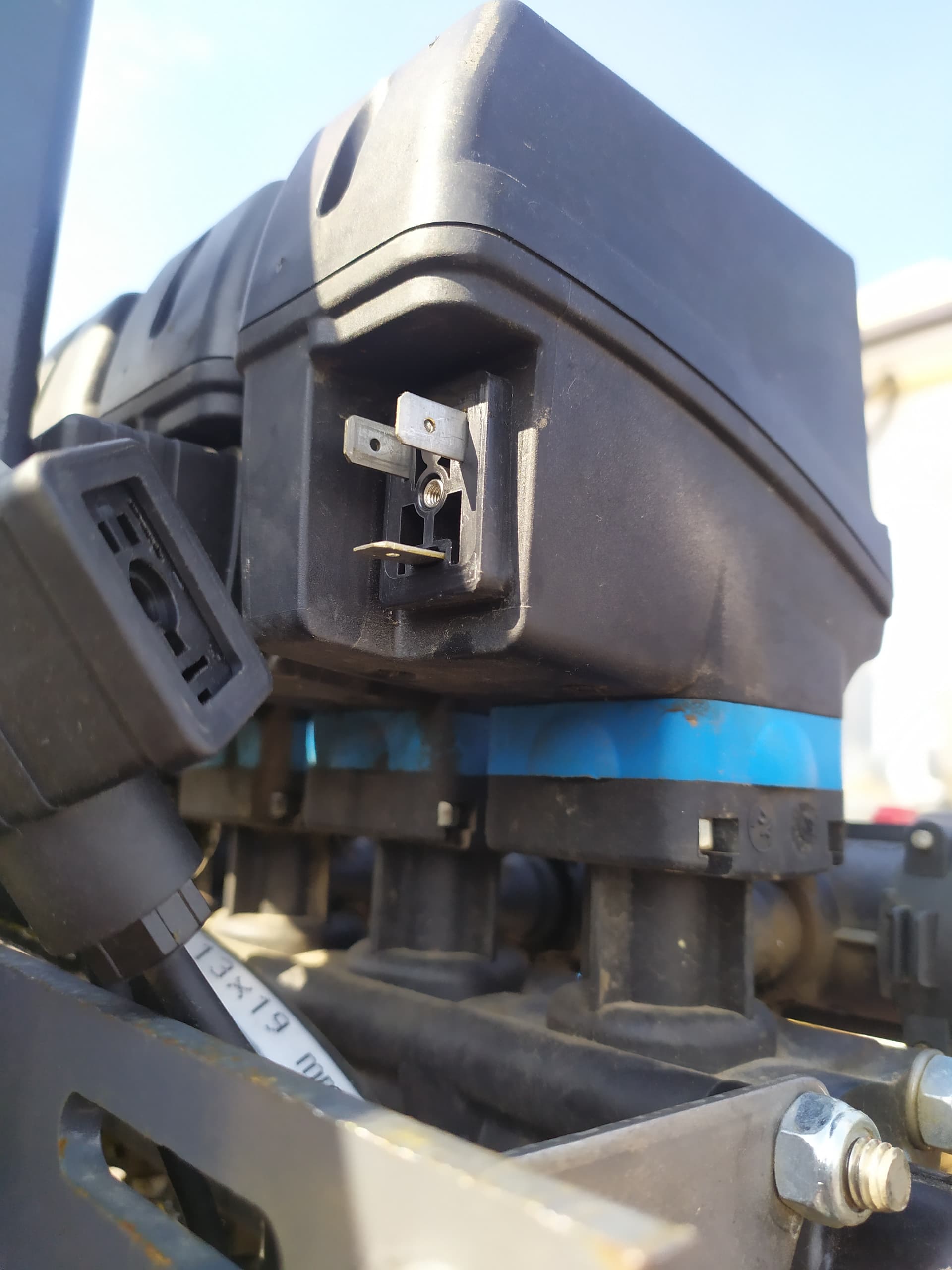
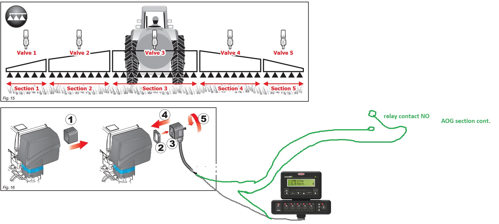
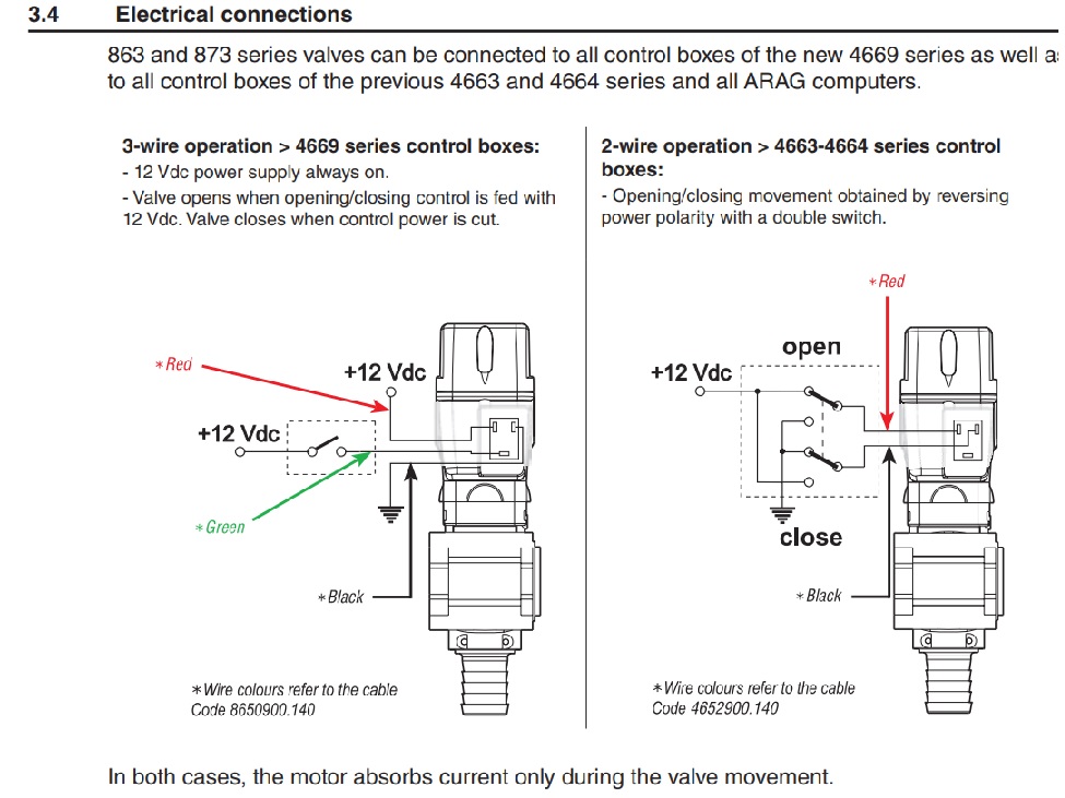
Hello, I spent a lot of time with the bravo series, your valves are probably the left valve type, that is, 3 wires, + and - go directly to the valve and when the voltage comes from the green 12 volt trigger tip, the valve opens, so it does not work as + - or - +! I would do this: strip the wire connected to the valve socket and remove the green wire, and connect the green wire in series to the relay contact on the aog section control board, in which case the switches on the bravo 180 controller should be in the up position (on)
1 Like
CommonRail, whiterose thanks for the answers. Now I will understand the connection.
In my case, the solenoid valves are turned on / off by changing the polarity of the voltage. Ie +/- - / +. I’ve tested how they work. As shown in figure 2.
Very interesting, all I looked at was 3-wire, this way you can connect directly to the aog section card, but to run the ratio control, the physical switches on the original 180 control must be turned on.
I need speed, the expense is tied to it. The speed sensor is standing.
Now I’ll go and see how the solenoid valves work.
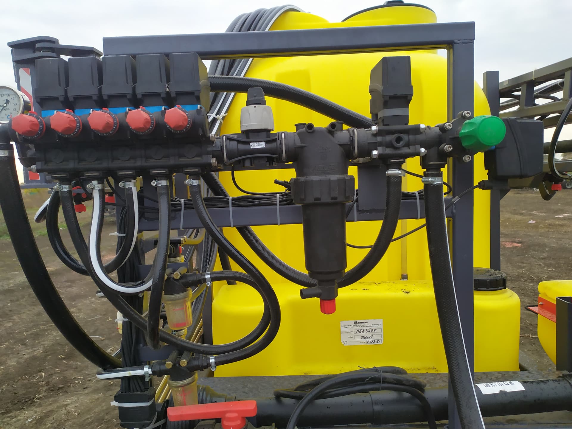
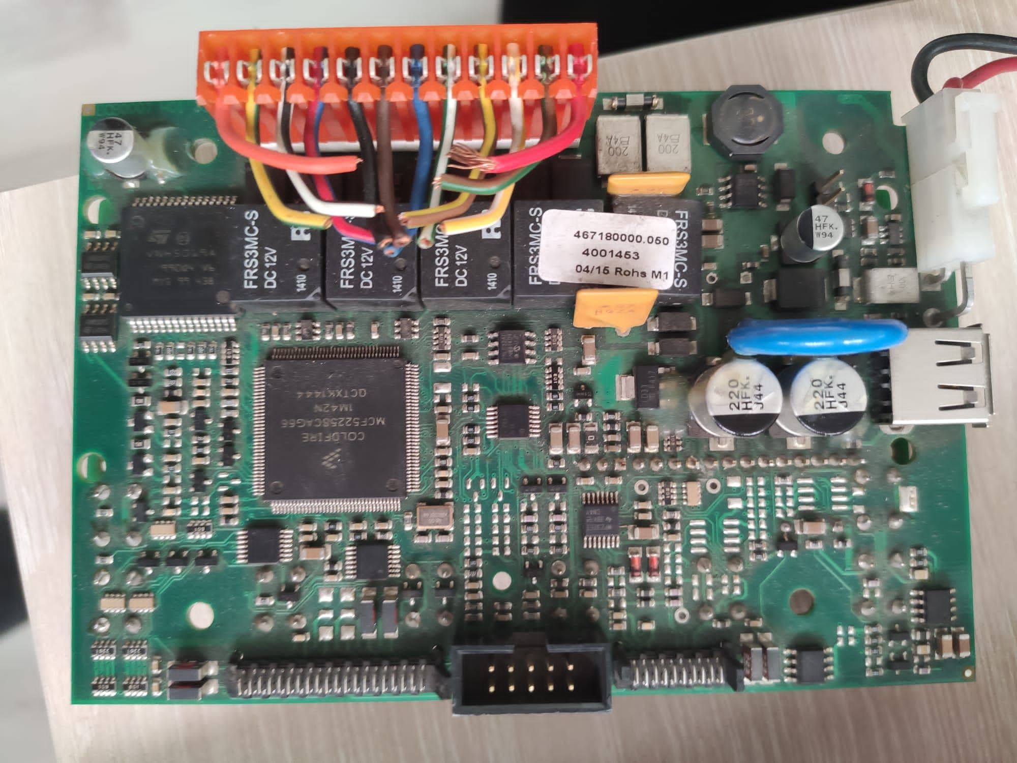
The socket on the right side of the controller is the gps input socket, and it works as rs232, I never had the opportunity to try it, maybe you can convert the speed information from simplertk to rs232 and enter this socket. You can see section relays in the photo. The bottom photo is the gps input socket.


1 Like

Sorry to mislead you, but all the bravo 180 series I’ve looked at for the last 6 years have been 3 wires, only proportional engine valve 2 wires.
I will not be able to convert the speed information from simplertk to rs232 and enter this connector, since this is a dark forest. I would like to make it easier.
Then use the wheel inductive sensor for speed information, and for section control, can’t you remove the controller and disconnect the cable from the physical switches and connect it to the AOG section control?
It is necessary to somehow do something so that the switching on and off of the sections would be done by AgO instead of mechanical switches. I don’t know how to do this yet. I will disassemble and see how the switches are connected.
As I will understand, I will try to connect 1 section to AgO.
Disassembled. It looks like information goes to the controller from the switches. Enabled or Disabled. I’ll watch it in the evening.

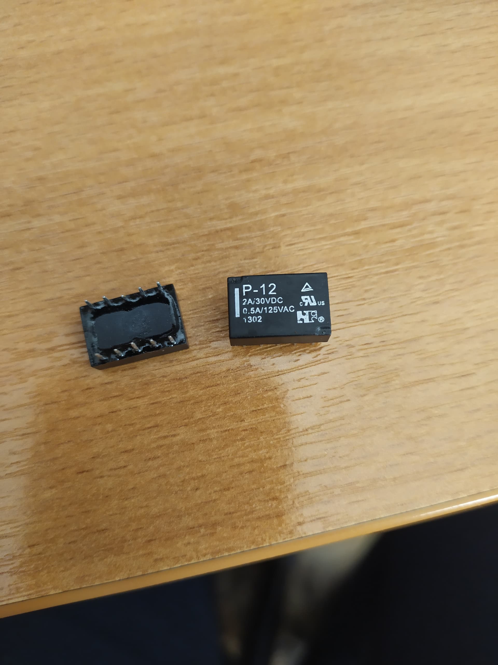
And if you remove the switches, and connect the DPDT relay in their place, so that they turn on from AgO. It is the switches that reverse the polarity. And for the controller there will be the same information. Enabled or Disabled.You just need to try what current the electrovalves consume.There are such relays.
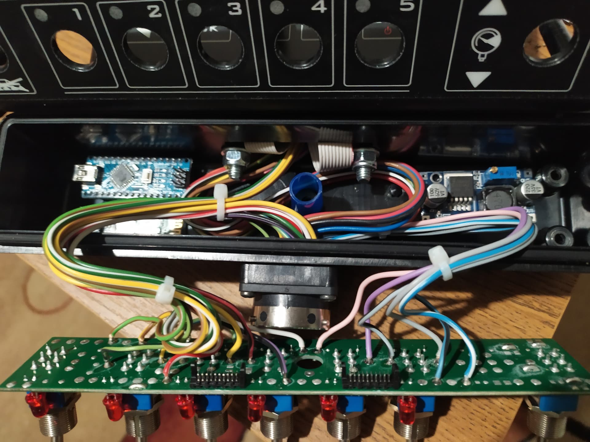
I decided to remove the section switches. And put the DPDT relay so that they are controlled from AgO. The BRAVO control unit includes ARDUINO, BLUETOOTH, POWER, UDN2981. With the section switches it is not clear yet. While I turn on the car. If you put buttons to close the holes where the switches were, but there you need to change the code so that the sections are switched on from the button. I don’t know how to do it yet. And yet, I don’t need some elements in the circuit. If I remove them, will the circuit work?

1 Like
There is a possibility to close the operation by Manuel and by Agopen. Something is tinkered with. I don’t know who it was anymore. He used mini servo, they mechanically switched the Bravo switch on and off. There’s a video I can’t find. Maybe a solution?
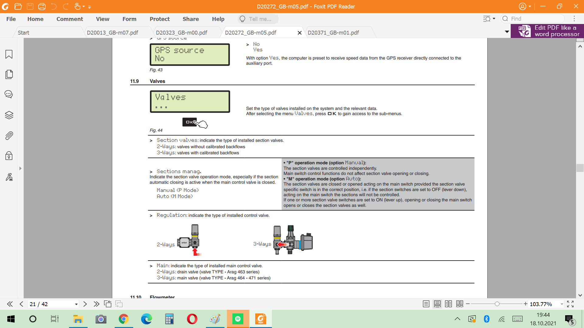
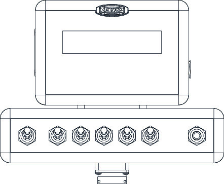
The switches in the Arag control have 3 tasks, 1- They turn on the LED on the panel 2- The boom length depends on the switches (If the boom is 15 meters, 5 sections will be calculated as 3x5 = 15 meters, if 4 switches are open, it will be calculated as 12 meters.) 3- By opening the relevant relay, it will operate the valve. . If you want, I can send the Bravo 180 manual pdf to your e-mail address.