Hello everybody.
I built the standard all in one board v2.4 last year.
When I ordered the board (minimum 5) at JLCPCB, I asked for 2 to come assembled, and 3 bare boards were left.
At the end of the planting season I damaged the board .
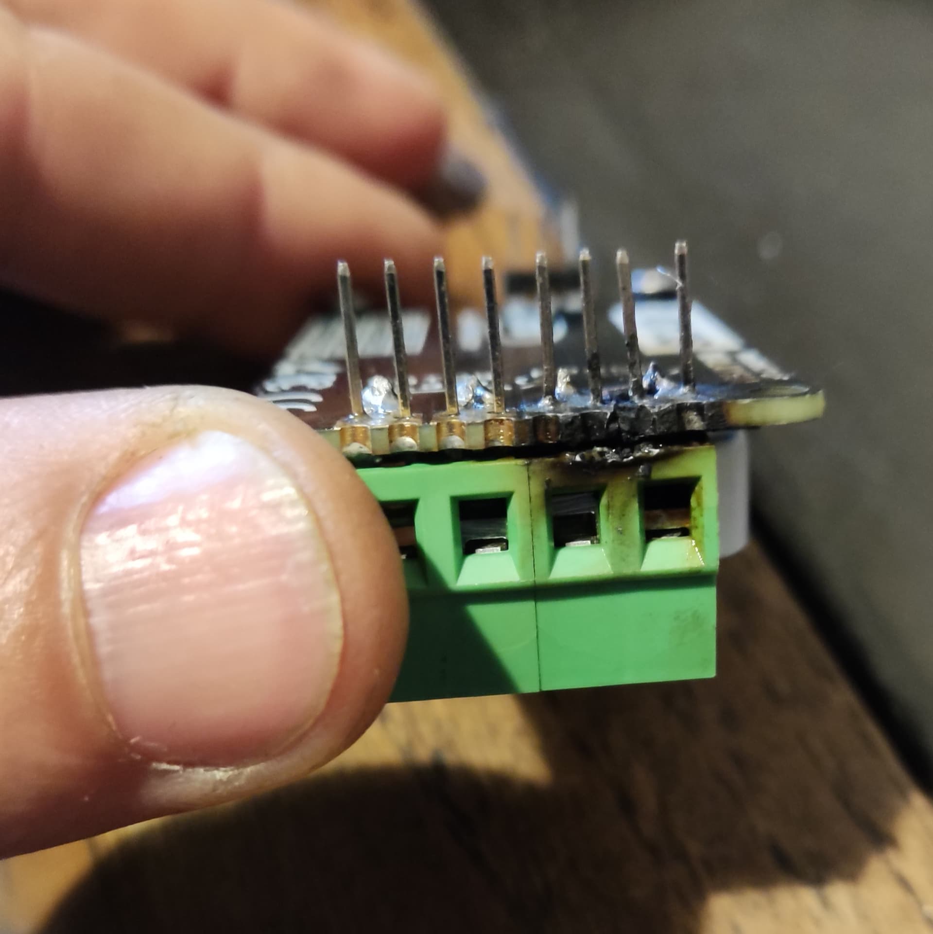
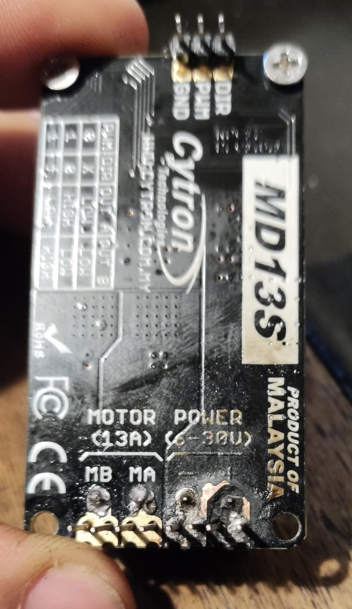
So, I exchanged the components for the other assembled board, but after some tests the cytron made a short circuit (still today I don’t know what happened, but I suspect that some solder or wire shorted out between the positive and negative on the cytron) and melted the board connections.
My question is:
Is it possible to assemble the remaining PCBs at home without using the microscope components?
If so, does anyone have a list of what components are needed to do just autosteer with an electric motor and two F9P antennas?
Or do I have to buy new boards from JLCPCB?
I assembled some components that JLCPCB didn’t have in stock, but they were almost all connectors, the 2 large capacitors, and the main plug.
I think I can do the assembly if the components are not the smallest
Can you post pictures of the top and bottom of both burned boards? Maybe someone can spot the issue before you spend more money on new boards and have them burn up as well.
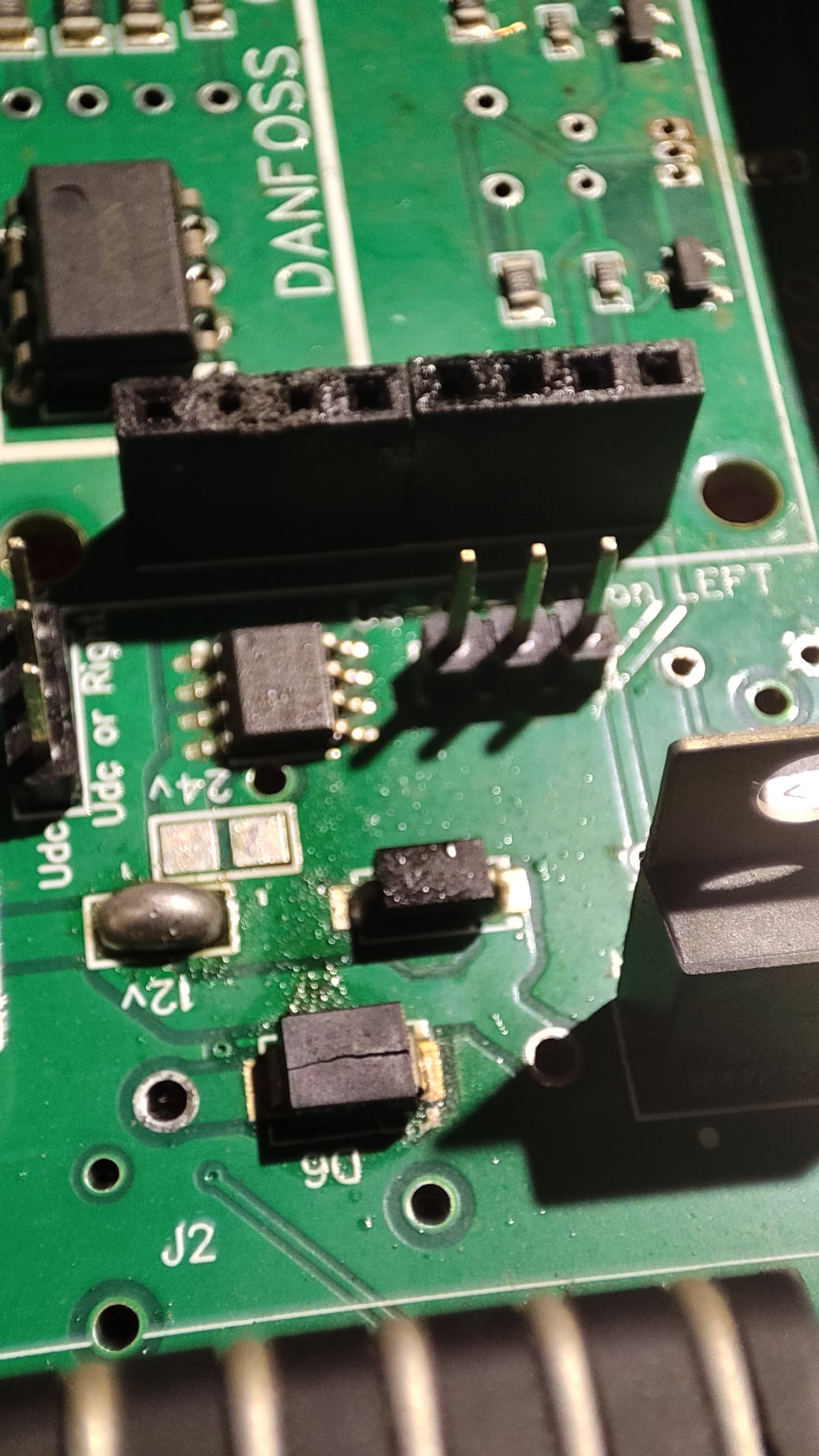
The components are all in the BOM list. You can check the schematics to see which SMD parts are equal to THT parts. Or just look at the silkscreen on bottom side. Should show D2 under D6 . So replace D6 with a THT diode 1n5401 which is a 3A diode ( Just mount on top side after removing the cracked D6) then replace the burned sockets, and if no traces are burned, the board should work again. Hoping the current chip is not damaged.
If you were to solder a new board with THT components, you don’t need any components in the danfoss area, but it might be difficult to solder the current chip. But can be replaced with a small current sensing board. Always remember to have a fuse of like max 10 A ( the way you use the 12 V to cytron everything has to pass that 3A diode)
Good question, and by the look of the MA and MB solder joints, they have not been heated long enough to float out and get shiny. So maybe the fault have started with cold solder joints at + and - . Making pins heat up then melting solder which then float across + and - , possible as we see solder have run through one of the + pin.