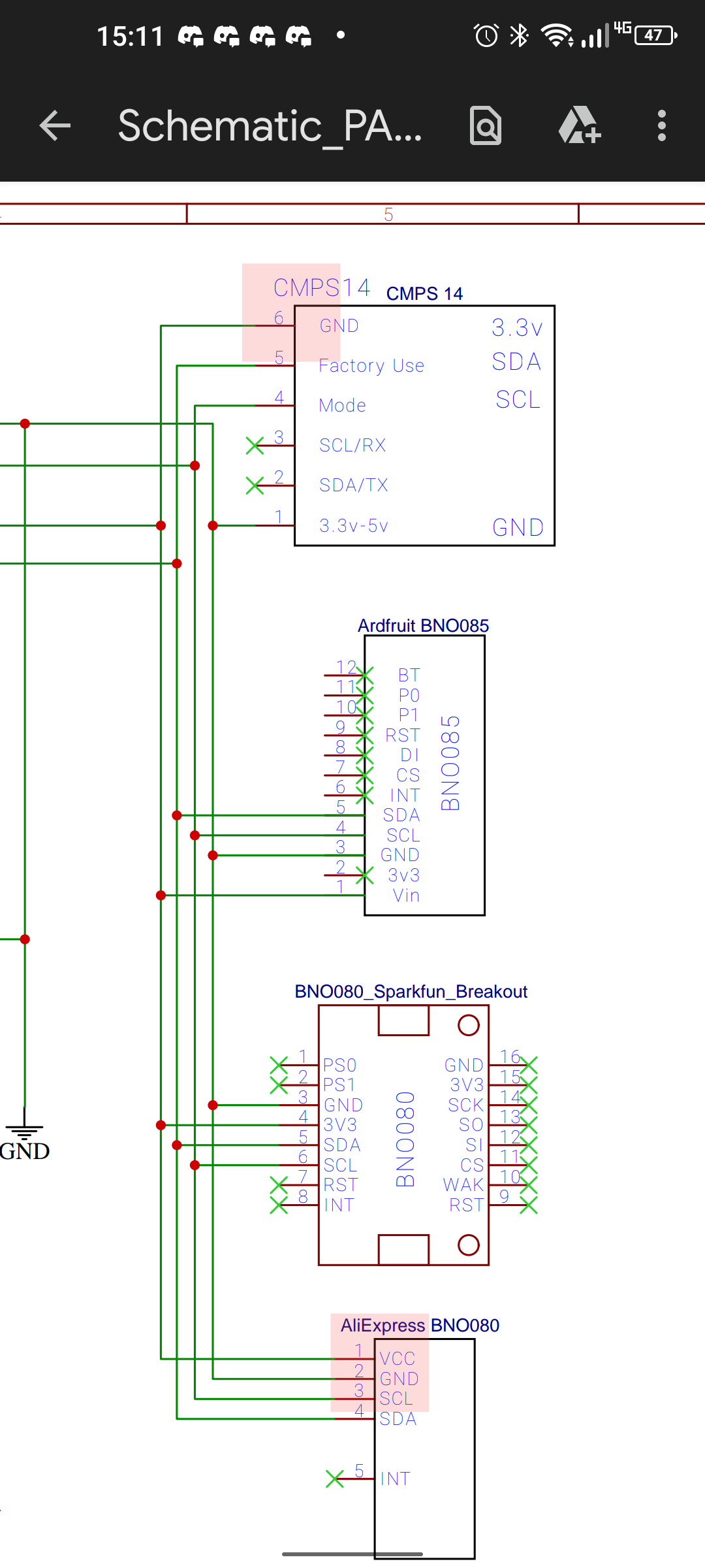
My BNO and teensy have arrived. I have gotten into the schematics to try and make my own breadboard panda system. I think this is the correct schematic for me to use, but it appears to me that the schematics short VCC and GND if you actually build it as specified. Relevant parts highlighted.
I won’t be building any of that part anyways because all I am putting on the board is the BNO and the gps. But for the sake of correctness and for the sake of asking if I’m using the correct schematic I thought I would draw it to someone’s attention.
Sometimes it is tricky in EDA software to flip a component upside down and the work-arounds are not always pretty, looks like that is maybe what happened here? How does the routing of the traces on the board actually appear?
If you flip the component in the schematic like this then everything is ok. Factory use and Mode are NC, SDA, SCL, 3.3v, and gnd all connected properly.
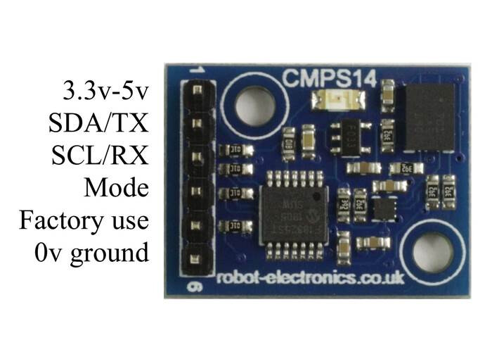
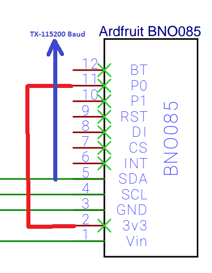
Definitely don’t trust a schematic for hookups. Look at what the pins are labeled on the BNO board. VCC is 3.3v, GND, and then if you connect p0 to 3.3v, the SDA pin becomes the serial TX. In that mode, it is hard coded to do 115200 baud, and transmits data 100 times a second.
Really?
The schematic should be your one source of truth!
Otherwise in 2 years when you have to troubleshoot you’ll be tying yourself in knots
I find it hard to believe you can’t do back-side components in EasyEDA. In Kicad you just have to press f
Ya should have been more clear. I just mean he shouldn’t trust that schematic he came up with. Always look at the data sheets, look at the official schematics, and the other documentation and ensure you’re doing it right. A schematic that clearly shows reverse polarity on the power and ground is definitely something to question.
I get a lot of mileage from a cheap Zeeweii DSO1511G when I’m not sure if I have RX and TX right. Most signals that you’d come across with AOG, or hobby stuff in general is no more than a few tens of MHz.
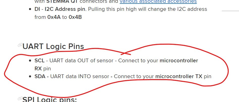
Ha I never noticed that before. The pages that picture the hookup do show it correctly. I went on the Adafruit forum and posted it so hopefully someone at Adafruit sees it and corrects the pinout page.
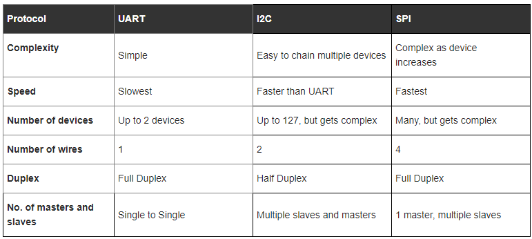
We are moving to use Serial UART_RVC mode for BNO because it is much faster then the overly bloated SHTP comm they use with i2c. Simple library, just read the values. Super stable and easy.
Also in the Teensy, I2C blocks the whole time it is waiting for the device to finish sending. Serial is a hardware buffer, non blocking. Those aren’t in the list of advantages and disadv.
the UART_RVC mode: it obviously requires a code modification that you are certainly doing…
and to respond to me and to others, I certainly looked at how to obtain this mode. BNO side it’s very simple just a small spot of welding on the back.
On the other hand, on the teensy side if I look closely at the diagram, it’s a shame that the BNO is on SCL/SDA0 and the ADS1115 on SCL/SDA1 and not the other way around (because on scl/sda1 there is also uart4). because it will take more than a code modification but also pcb and connections, right?
Just a correction. I did not " come up with " this schematic. It’s from the official GitHub repo. That’s why I posted it here. If I made a mistake on my own drawn schematic I would just fix it and not tell anyone…
Does AOG use more than just the heading and roll from the BNO? If a person wanted to get really fancy (like they do on drones) you could calculate updated position information between Gps fixes based on IMU data.
Have you ever looked into the ardupilot/pixhawk system? I haven’t popped in on them for a few years. But I believe they implemented this years ago because you will crash drones if you don’t.
That is the unfortunate inevitability of developing a system like this in the PCB-type way. But in any case, iteration is always harder in hardware. That’s why it’s not called easyware.
I guess just be thankful your ADS and your BNO and your microcontroller aren’t all SMD soldered into one PCB. You can pull the modules off the mother board and make a new one.
With the serial BNO we can also get Angular velocity and 3D accelerations. But tractors, unlike drones don’t go sideways or up and down very quickly so the model is thankfully much simpler.