I’ll have a look thanks.

I’m tearing my hair off for some days now in a vain endeavour to get a UM982 to show traces of proper RTCM signalling.
The idea was as follows:
- Take our local public Bavarian ntrip provider coined LFPS
- Take some ntrip client (BKG, UPrecise, lefebre, AgOpenGPS…) and feed RTCM to the UM982
- enjoy at least fix quality 5 (RTK float) and at decent air conditions, quality 4 aka RTK fix in $GNCGA messages
- … and RTK-LED’s on the EVB-style board
- learn, understand, plan, proceed…
Sadly, things do not work that way.
$GNCGA is nailed to quality1. No RTK LED on the UM982 board.
$GNGGA,194448.00,4959.05638934,N,01215.59984075,E,1,10,1.5,541.8653,M,47.0442,M,,*71
....
$GPGSV,2,1,06,13,41,286,26,07,48,062,26,20,54,224,32,09,14,105,17,1*6D
$GPGSV,2,2,06,30,83,097,27,05,54,284,24,1*6D
$GPGSV,1,1,01,07,48,062,18,4*56
$GPGSV,1,1,02,09,14,105,19,30,83,097,29,8*62
I tried different casters from rtk2go.com, but either they don’t even start, or drop out after some minutes.
I have 2 other (even cheaper) China-RTK-bragging-modules (UM626N and LC29H). At least occasionally they go to fix quality 5 at some rtk2go casters.
And compared to the UM982, they note more satelites (~25 instead of ~12) and lower HDOP (typ. 0,5 m insteasd of 1,5 m) in the PVT solution.
Anyway. I target to cm precison with tool steering, so UM982 is first priority.
How can I kindof debug RTK what’s going on?
Just some ideas:
- LFPS either supports RTCM 3.1 or 3.4, nothing inbetween
may there be compatibility problems? - decoding raw logs, I see the lines are terminated by 0A only (Linux LF style NL), not 0D-0A (CR-LF Windows NL style)
- Do I need good sky view to even switch from PVT to RTK float? (still waiting for SMA cable to put my UM982 test antenna to rooftop…)
- May I have burned RXD1 while fiddling with interfacing?
how can I check?
They have summer sales at ali now, so I ordered a UM980 base station kit.
May be it’s best to go with an own base station, anyway?
So I can expect proper compatibility and enjoy 3 Bands?
This last bit about burning RXD1 is kind of odd. Why would you say that? What were you doing to the module to make you think you burned RXD1? Did you send RS232 to the UART port? The com ports on this module and most others are TTL 3.3v not RS-232.
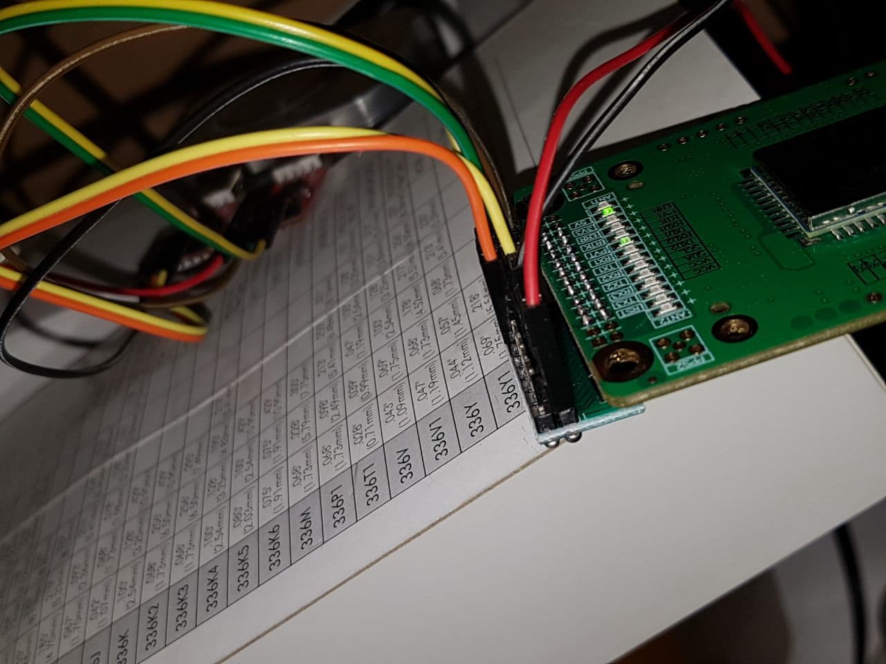
Which UM982 board do you have? Picture please.
This is the board - I hope ± close to the EVB you are using.

(ah, it’s the forum that converts all aliexpress links to dutch - why - never mind … )
The aliexpress links you posted far above are not available any more.
There are a couple of GNSS shops at ali now, many of them turning out as affiliates of the same EMAX ltd in Shanghai.
OK - you asked for the long story ![]()
![]() : - here it is:
: - here it is:
I started testing with some ordinary PL2303 cable.
When I only connected TXD1, I could read NMEA sentences.
As soon as I connected RXD1, NMEA stopped, as did the PVT LED
trying … fiddling … different serial adapters … DuPont-cables with funny color mixed … f’#§$%"d … quite sure to connect RXD / TXD the wrong way …
Suspected that the USB cables might not deliver sufficient current.
Attached the module to a laboratory power supply,
Usually it takes ~ 200 mA, but sometimes was up to 1000 mA.
So I was afraid that 800 mA going some wrong way may have damaged ports.
But glad to see that those green boards have a lot of protection circuitry.
Now I have two CP2102 and the Lab Power attached.
I can read NMEA from TXD1, issue commands and get responses on COM2.
Next test: cat some arbitrary garbage into RXD1. See the RXD LED flashing, and TXD1 complaining about the garbage. So I may be I have burned some UART converters, but luckily not the UM982 module.
My primary test envionment ist debian10, close to metal.
stuff like this (not all on the same console)
lsusb
sudo dmesg
stty -F /dev/ttyUSB1 115200 -echo -icrnl
stty -F /dev/ttyUSB2 115200 -echo -icrnl
cat /dev/ttyUSB1
cat /dev/ttyUSB2
echo mode > /dev/ttyUSB1
delivers e.g.:
$command,mode,response: OK*5D
#MODE,97,GPS,FINE,2371,213691000,0,0,18,600;MODE ROVER UAV,*4E
$command,version,response: OK*24
#VERSION,97,GPS,FINE,2371,213708000,0,0,18,149;UM982,R4.10Build11826,HRPT00-S10C-P,2310415000012-LR23A6242132384,ff27d890eb0f3f4e,2023/11/24*8756c734
$command,config,response: OK*54
$CONFIG,ANTENNA,CONFIG ANTENNA POWERON*7A
$CONFIG,NMEAVERSION,CONFIG NMEAVERSION V410*47
$CONFIG,RTK,CONFIG RTK TIMEOUT 600*69
$CONFIG,RTK,CONFIG RTK RELIABILITY 3 1*76
$CONFIG,PPP,CONFIG PPP TIMEOUT 120*6C
$CONFIG,HEADING,CONFIG HEADING RELIABILITY 3*67
$CONFIG,HEADING,CONFIG HEADING FIXLENGTH*6F
$CONFIG,HEADING,CONFIG HEADING LENGTH 0.00 0.00*38
$CONFIG,DGPS,CONFIG DGPS TIMEOUT 600*69
$CONFIG,RTCMB1CB2A,CONFIG RTCMB1CB2A ENABLE*25
$CONFIG,ANTENNADELTAHEN,CONFIG ANTENNADELTAHEN 0.0000 0.0000 0.0000*3A
$CONFIG,PPS,CONFIG PPS ENABLE GPS POSITIVE 500000 1000 0 0*6E
$CONFIG,SIGNALGROUP,CONFIG SIGNALGROUP 4 5*05
$CONFIG,ANTIJAM,CONFIG ANTIJAM AUTO*2B
$CONFIG,AGNSS,CONFIG AGNSS DISABLE*70
$CONFIG,BASEOBSFILTER,CONFIG BASEOBSFILTER DISABLE*70
$CONFIG,COM1,CONFIG COM1 115200*23
$CONFIG,COM2,CONFIG COM2 115200*23
$CONFIG,COM3,CONFIG COM3 115200*23
I also can send commands to COM1 and get the response mixed into the NMEA stream then.
So let’s assert that RXD1 is NOT burned ![]()
![]()
![]()
Ok. That board has 3 uarts so let’s use com2. Send your RTK corrections to com2. Look for the led to flash in time with the corrections being sent. Usually every 1 second. Once you corrections going in hook up a serial terminal to com3. I like CoolTerm but whatever terminal works for you is fine. Make sure you are on com3 and issue RTCMSTATUSA ONCHANGED command. You should see the status output every time your corrections are sent. Paste the output here.
Just because the Led is flashing for rxd1 doesn’t mean the data is reaching the pin on the chip. I don’t recall where the protection diode is in relation to the led. If it is after the led, the led will still flash but no signal will get to the chip.
Of course. But at least the input at board level - the first victim in case of mistreatement - is checked thus.
But as I said, I get complaints on TXD1 when I send garbage to RXD1 - and TXD flashes more intensive than the normal 1 Hz NMEA.
And I can even request $config on TXD1 by RXD1 - thus I’m qhite confident that RXD1 arrives at the chip.
OK, did it slightly different, …
- have not yet wired COM3, since I just misused 2mm JSP to map to Du-Pont.
wait for decent 2.0-to-2.5-adaptor boards - did it the linux console way
- put a watching console on COM2
- issue a “RTCMSTATUSA ONCHANGED” to com2
- attached “BKG Ntrip Client (BNC)” to com1, since it wants to read and forward NMEA to the caster
and I get messages like
#RTCMSTATUSA,97,GPS,FINE,2371,238132000,0,0,18,251;1032,98,2215,0,0,0,0,0,0,0*9d51fe28
#RTCMSTATUSA,97,GPS,FINE,2371,238136000,0,0,18,251;1033,99,2351,0,0,0,0,0,0,0*53dbd466
#RTCMSTATUSA,97,GPS,FINE,2371,238136000,0,0,18,251;1005,100,2351,0,0,0,0,0,0,0*9f9c6d40
#RTCMSTATUSA,97,GPS,FINE,2371,238136000,0,0,18,251;1032,101,2351,0,0,0,0,0,0,0*fe0ed722
#RTCMSTATUSA,97,GPS,FINE,2371,238136000,0,0,18,250;1033,102,2352,0,0,0,0,0,0,0*a2f84c92
#RTCMSTATUSA,97,GPS,FINE,2371,238136000,0,0,18,250;1005,103,2352,0,0,0,0,0,0,0*424f93d7
#RTCMSTATUSA,97,GPS,FINE,2371,238136000,0,0,18,250;1032,104,2352,0,0,0,0,0,0,0*a7feb460
#RTCMSTATUSA,97,GPS,FINE,2371,238141000,0,0,18,251;1033,105,2216,0,0,0,0,0,0,0*2182be0c
#RTCMSTATUSA,97,GPS,FINE,2371,238141000,0,0,18,251;1005,106,2216,0,0,0,0,0,0,0*0bfb17c5
#RTCMSTATUSA,97,GPS,FINE,2371,238141000,0,0,18,251;1032,107,2216,0,0,0,0,0,0,0*6a69ada7
#RTCMSTATUSA,97,GPS,FINE,2371,238141000,0,0,18,251;1033,108,919,0,0,0,0,0,0,0*b5e1436c
#RTCMSTATUSA,97,GPS,FINE,2371,238141000,0,0,18,251;1005,109,919,0,0,0,0,0,0,0*d7d71866
#RTCMSTATUSA,97,GPS,FINE,2371,238141000,0,0,18,251;1032,110,919,0,0,0,0,0,0,0*42548f7b
#RTCMSTATUSA,97,GPS,FINE,2371,238147000,0,0,18,251;1033,111,1402,0,0,0,0,0,0,0*d00a7808
#RTCMSTATUSA,97,GPS,FINE,2371,238147000,0,0,18,251;1005,112,1402,0,0,0,0,0,0,0*fa73d1c1
#RTCMSTATUSA,97,GPS,FINE,2371,238147000,0,0,18,251;1032,113,1402,0,0,0,0,0,0,0*9be16ba3
In the log window of NKG ntrip client, I read
25-06-17 18:14:38 FPS_BY_RTCM3_2G: NetQueryV2: server replied: OK
25-06-17 18:14:38 FPS_BY_RTCM3_2G: Data timeout, reconnecting
25-06-17 18:16:02 FPS_BY_RTCM3_2G: NetQueryV2: server replied: OK
25-06-17 18:16:02 FPS_BY_RTCM3_2G: Data timeout, reconnecting
25-06-17 18:17:12 FPS_BY_RTCM3_2G: NetQueryV2: server replied: OK
25-06-17 18:17:12 FPS_BY_RTCM3_2G: Data timeout, reconnecting
The ntrip client occupies COM1, but I can log NMEA output to a file and can see e.g.:
$GPGGA,182331.00,4959.05694993,N,01215.60047505,E,2,06,1.9,553.7993,M,47.0442,M,2.0,2466*49
$GPVTG,274.057,T,270.875,M,0.20158,N,0.37333,K,A*26
$GPGSV,2,1,06,30,55,201,24,20,55,290,25,11,32,239,27,06,15,206,23,1*62
$GPGSV,2,2,06,07,74,109,13,09,44,083,23,1*6F
$GPGSV,2,1,06,30,55,201,25,04,09,085,22,11,32,239,22,06,15,206,14,4*69
$GPGSV,2,2,06,07,74,109,24,09,44,083,20,4*6D
$GPGSV,1,1,04,30,55,201,30,11,32,239,28,06,15,206,23,09,44,083,18,8*65
$GBGSV,1,1,02,22,85,337,28,36,53,137,27,1*77
$GBGSV,1,1,02,22,85,337,21,36,53,137,21,8*71
$GAGSV,1,1,02,10,42,263,26,29,33,079,22,1*76
$GAGSV,1,1,02,10,42,263,26,29,33,079,26,2*71
$GAGSV,1,1,01,29,33,079,19,7*4F
$GNGGA,182332.00,4959.05580936,N,01215.59739111,E,1,10,1.6,557.6492,M,47.0442,M,,*70
OK, looks like my learning curve starts to rise…
- at least, some RTK arrives at the UM982, obviously
- I haven’t seen that “Data timeout” with LFPS before.
Is it a server side issue - I assume so
I’m on 300 Mbit fiber internet here… - flashing of RXD1 seems to be in line with #RTCMSTATUSA messages
- if RTK stuff arrives, PVT LED turns off, fix level in $GNGGA goes from 1 to 2
- when we have a data timeout, we come back to PVT and fix level 1
- never seen RTK LED flashing yet
- never seen fix level 4 or 5 yet
This is the current config of my ntrip client.
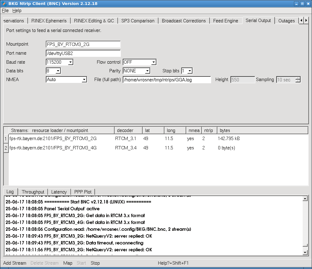
Afaik they need the actual position, since the correction signal is synthetically merged from different stations all over Bavaria.
That’s the reason for setting NMEA to “auto”
OK; tried the mountpoint 3_4G now, with RTCM_3.4 and GPS, Glonass, Galileo and BeiDou.
Obviously, UM982 undestands those messages as well
But still we see timeouts…
#RTCMSTATUSA,96,GPS,FINE,2371,240224000,0,0,18,251;1033,894,2733,0,0,0,0,0,0,0*51bc357c
#RTCMSTATUSA,96,GPS,FINE,2371,240224000,0,0,18,251;1005,895,2733,0,0,0,0,0,0,0*b10bea39
#RTCMSTATUSA,96,GPS,FINE,2371,240224000,0,0,18,251;1032,896,2733,0,0,0,0,0,0,0*1a5726d7
#RTCMSTATUSA,96,GPS,FINE,2371,240225000,0,0,18,252;1124,127,2733,5,0,5,0,5,0,10*1dc04800
#RTCMSTATUSA,96,GPS,FINE,2371,240225000,0,0,18,301;1094,90,2733,9,9,9,9,0,9,0*75c4c04d
#RTCMSTATUSA,96,GPS,FINE,2371,240225000,0,0,18,301;1084,99,2733,4,4,0,4,4,0,0*b7c02f33
#RTCMSTATUSA,96,GPS,FINE,2371,240225000,0,0,18,302;1074,93,2733,7,7,7,5,3,1,0*54c25976
#RTCMSTATUSA,96,GPS,FINE,2371,240225000,0,0,18,250;1033,897,2734,0,0,0,0,0,0,0*41005873
#RTCMSTATUSA,96,GPS,FINE,2371,240225000,0,0,18,251;1005,898,2734,0,0,0,0,0,0,0*db481575
#RTCMSTATUSA,96,GPS,FINE,2371,240225000,0,0,18,251;1032,899,2734,0,0,0,0,0,0,0*badaaf17
#RTCMSTATUSA,96,GPS,FINE,2371,240226000,0,0,18,252;1124,128,2734,5,0,5,0,5,0,10*d25477fd
#RTCMSTATUSA,96,GPS,FINE,2371,240226000,0,0,18,301;1094,91,2734,9,9,9,9,0,9,0*b3997f62
#RTCMSTATUSA,96,GPS,FINE,2371,240226000,0,0,18,301;1084,100,2734,4,4,0,4,4,0,0*8461fa4c
#RTCMSTATUSA,96,GPS,FINE,2371,240226000,0,0,18,302;1074,94,2734,7,7,7,5,3,1,0*16bc7b8c
#RTCMSTATUSA,96,GPS,FINE,2371,240226000,0,0,18,251;1033,900,1911,0,0,0,0,0,0,0*b8f26cfd
#RTCMSTATUSA,96,GPS,FINE,2371,240226000,0,0,18,251;1005,901,1911,0,0,0,0,0,0,0*5845b3b8
#RTCMSTATUSA,96,GPS,FINE,2371,240226000,0,0,18,251;1032,902,1911,0,0,0,0,0,0,0*f3197f56
#RTCMSTATUSA,96,GPS,FINE,2371,240227000,0,0,18,252;1124,129,1911,5,0,5,0,5,0,10*73b815f0
#RTCMSTATUSA,96,GPS,FINE,2371,240227000,0,0,18,301;1094,92,1911,9,9,9,9,0,9,0*a28c085a
#RTCMSTATUSA,96,GPS,FINE,2371,240227000,0,0,18,301;1084,101,1911,4,4,0,4,4,0,0*b99089ed
#RTCMSTATUSA,96,GPS,FINE,2371,240227000,0,0,18,302;1074,95,1911,7,7,7,5,3,1,0*cd677a38
Looks like for serious applications, I have to build my own base station… ![]()
I don’t know what your caster is sending but it doesn’t look like RTCM v3
They claim it being RTCM 3.4
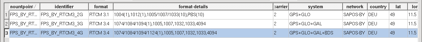
…scroll down to “Multiple Signal Messages (MSM) Message Types”
so I try the first mountpoint with RTCM 3.1 again?
Or is there any other caster available for testing purposes until I get my own Base?
Looking closer I see those are all MSM4 standard precision messages. High precision RTK needs MSM 6 or 7 messages.
You can look on rtk2go, centipede or RTK.data for a caster nearby, less than 20km.
OK, so no use in the RTCM3_2G mountpoint of LFPS, anyway.
I’ m waiting for a UM980 base station set from China, hope this will be able to supply the proper data.
Absolutely! A base of same type should be able to deliver the correct messages.
But there’s not much F9P killer about um needing a base as close as 20 km and not accepting MSM4.
My F9P get rtk fix on MSM4 even with a base as far away as 90 km. Of course that distance would result in less precision, but still rtk fix, rover antenna is the standard 2 band ublox.
Is your antenna of correct 3 band type for um? Possition under open sky and away from building?
Also I think it is good to spell out: IF base only output messages from one constellation, let us say GPS, and your rover is set to look only for glonas satellite. Then there is no way to get rtk, as that requires messages from around 8 SAME satellites.
I would question your antenna, placement or quality or even the antenna cable. According to the gga message you are only tracking 6 to 10 satellites, this seems very low for a um982. I have noticed if the um doesn’t track enough sats or has bad sat signals it doesn’t even try to use the rtcm data to resolve a fix.
As for msm4 or msm7. I have um982 running fine with msm4. Maybe msm7 would be better for height, I know the survey guys around here use msm4 in there network.
Agree on improper placement.
However, with the same antenna and placement, other even cheaper modules get > 20 sats and a HDOP of ~ 0.5.
It’s a “STA-901A”
GPS: L1/L2/L5
GLONASS: L1/L2/L3
BDS: B1/B2/B3
Galileo: E1/E5/E6
Looks the same as HA-901A quadrifilar helical antenna
Don’t know the difference, maybe the STA is inferior?
Anyway, I don’t consider them as mechanically stable enough, on a tractor roof, ploughing through the bushes.
And yes, the adapter cable is a bit loose at ANT1, but I don’t see changes in SNR when moving it-
Just got my SMA cable and had to learn that there are two different types with reverse direction of the inner pin ![]()
![]()
Looks like I have to wait for another shipment from China to get the right one…
Wait for some AG30, which I found reported as fine.
Got some mail from igs-ip.net, so may be I’ll find a proper ntrip caster for testing there…
Yes, SMA-RP are for wifi antennas.
desperate for some feeling of success…
Attached an LC29H to the rooftop antenna of an UM626 kit.
And got my first RTK fix since long ![]()
![]()
![]()
Unearthed my junk box from rtklib experiments a decade ago and found coax crimp stuff there. Will have to learn how to build cables that fit ![]()
OK, with my rooftop antenna I get a RTK fix within seconds.
40 satellites, SNR values ~50,
looks like “milestone passed” ![]()
![]()
$GNGGA,182510.00,4959.05825866,N,01215.59791588,E,4,40,0.4,554.5264,M,47.0442,M,1.0,831*6F
$GPGSV,3,1,11,05,32,308,45,06,09,204,41,07,72,087,47,09,38,087,43,1*60
$GPGSV,3,2,11,11,28,234,44,13,16,269,35,16,08,028,39,20,59,281,49,1*63
$GPGSV,3,3,11,21,,,47,30,62,201,48,14,05,167,36,1*69
$GPGSV,2,1,06,06,09,204,45,09,38,087,49,11,28,234,50,21,,,52,8*5E
$GPGSV,2,2,06,30,62,201,51,14,05,167,40,8*6F
$GLGSV,2,1,08,66,39,094,46,82,12,243,40,77,53,138,43,76,46,054,48,1*7B
$GLGSV,2,2,08,83,25,293,43,67,69,344,48,68,24,300,42,78,07,182,45,1*7D
$GBGSV,3,1,12,05,18,125,39,06,10,048,34,09,26,050,38,16,07,047,37,1*7F
$GBGSV,3,2,12,20,11,297,39,23,47,163,48,24,07,036,39,25,50,075,49,1*79
$GBGSV,3,3,12,29,09,306,33,37,07,197,43,41,52,114,47,32,67,301,51,1*7A
$GAGSV,3,1,11,04,81,318,49,09,30,272,47,10,23,211,47,11,36,240,45,1*70
$GAGSV,3,2,11,19,34,081,42,21,30,071,45,36,32,302,47,06,55,277,49,1*7C
$GAGSV,3,3,11,27,07,024,40,23,25,130,46,12,,,35,1*76
$GAGSV,3,1,09,04,81,318,31,09,30,272,29,10,23,211,28,11,36,240,27,2*70
$GAGSV,3,2,09,19,34,081,24,21,30,071,29,36,32,302,29,06,55,277,31,2*7B
$GAGSV,3,3,09,23,25,130,27,2*4E
$GAGSV,3,1,11,04,81,318,46,09,30,272,46,10,23,211,43,11,36,240,41,7*78
$GAGSV,3,2,11,19,34,081,39,21,30,071,42,36,32,302,45,06,55,277,48,7*72
$GAGSV,3,3,11,27,07,024,35,23,25,130,42,12,,,38,7*7B
$GNVTG,191.560,T,188.379,M,0.00230,N,0.00425,K,D*3C
over at Win, I think UPrecise tells me that we have not yet 3-Band operation, right?
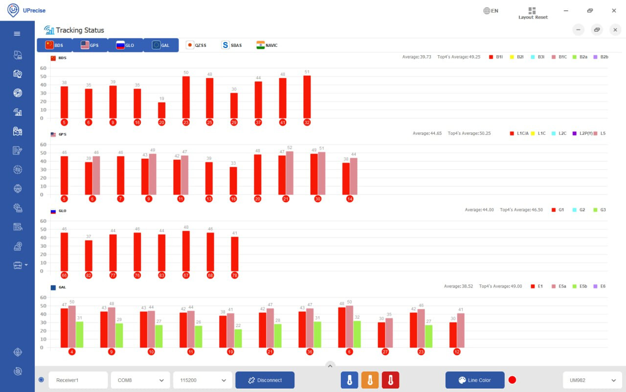
Ah, I see that L2 is the outlier in the freq band.
Have to switch antennas…
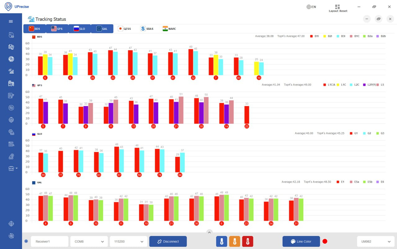
what a difference…
Looks good at the first glance, but short before clicking the order button, I realized that it had only one USB UART - the other one is simply for power.
Do you use this board on the tractor?
If so, is the connection of USB-power, USB-communication and antennae reliable?
Is USB-C sufficient for reliable power?
(USB-A I found is not.)
Is it possible to power the tablet over this board?
For the testing desk, I found those tiny 2x10 2.0-to-2.54-mm adaptor boards which fit perfect.
Soldered a 2.0-mm header and 2x10 2.54-mm pins:
This way I can easily connect DuPont wires.
I have a view on top of the board, with the LED’s visible, and pinout identical to the manual.
Next step might be to insert Du-Pont-Wires into multifolds to avoid plugging errors and increase mechanical stability. This might even serve for first tests on the tractor.
Another option might be to solder the 2.54-mm field by through-hole wires to some standard prototype board and put other components (power, UART, mounting) there as well.