Have you seen the SMOOTH setting? what does this mean?
It seems to do a continuous rolling average of the past N seconds of readings. I tried it and it made the GPS appear to lag behind the actual position slightly. I tested it with google maps which are not the most accurate either. The path on the map did look smoother.
Might be useful for folks using the slow poke version of AOG since they are moving at a snails pace.
Slow poke is pretty much done and committed, well past worrying about slow speed now ![]()
if I may ask, do you have any direct line with Unicore? How are you getting those docs and firmwares?
The manuals are available on the Unicore public site. Make sure you are on the English site versus the Google translation of the Chinese site. There are more items available for download on the English site. The english site URL’s start with “en”.
Also, the manuals can be quite long and sometimes less than clear so read them carefully and completely. There is a lot of good info in the 300 page command manual. They can be out of date with regards to build numbers or model numbers that support a function so you just have to try the function sometimes.
1 Like
Is it correct that UM982 cannot roll in contrast to Dual F9P?
regarding dual antenna roll angle, see: Is the UM982 an F9P killer for AOG? - #38 by chri5k
To clarify, the F9P calculates the North East Down (NED) vector and baseline between the position receiver (moving base) and the heading receiver. This information is encoded into a NAV-RELPOSNED packet. The AOG firmware uses the information in this packet to calculate dual roll . The firmware only uses the results of the calculation when the receiver has an RTK Fixed solution. This can be found in the zRelPos.ino file in the AOG firmware repository.
The UM982 outputs Earth Centered Earth Fixed (ECEF) coordinates for the position antenna and the heading antenna. There are c++ routines for converting ECEF coordinates into a NED vector and baseline on the Teensy. This data can be used to calculate roll in the same manner as the F9P.
Attached are the c++ coordinate conversion routines header file I have been using. I did not create these routines. Someone way smarter than me created them and posted them on OnlineGBD. I did check the formulas against the NOAA references and they appear to be correct. I also changed the floats to doubles since the Teensy handles doubles with more precision.
conv_coord.h.zip (4.4 KB)
1 Like
What VCC (power supply voltage) is the UM982eb module good for? I’ve seen 3.3-7V and 3.3-5.5V. Also, what voltage levels are it’s IO?
edit
How much power does it need on the supply, is a 1A switching buck sufficient?
What “polarity” is pin 21 PVT_STAT?
The spec sheet for the evaluation board I have says min 3.3v and max 5.5v. The spec sheet for the UM982 chip says max 3.6v. I run mine at 3.3v. Min current for the evaluation board at 3.3v is listed as 150ma and max 250ma. The one I am running right now shows it is drawing 340ma.
COM port IO is at the LVTTL (3.3v) level. PVT_STAT is driven HIGH to VCC - 0.45 volts when positioning.
Thanks for those numbers. So I expect the eval board has a LDO or buck regulator. Are you running a bare chip or eval board? When you say “when positioning”, you mean it has a fixed/locked position? You’d use an LED to ground to indicate that it’s “working”?
I have an eval board. Looks like it has a regulator / buck of some sort.
By “positioning” I mean the UM982 is receiving satellite signals and is working on a position solution. I wouldn’t say fixed / locked since it could be producing a DGPS, RTK Float, Wide-lane or some other position solution. To me fixed means an RTK INT fix with sub-centimeter accuracy.
There is an RTK light on my eval board that lights up when it has an RTK fix of some sort, either float or int. Pad 25 on my board is for RTK_STAT but has no pin soldered in to it. I would put a current limiting resistor in series with the LED. Those outputs are good for something like 2 mA.
Earlier in this thread I posted all of the manuals and data sheets I have. The numbers are in those documents.
For me, the ByNav port on the AIO V5 board does not work with the UM982. The RX and TX ports are swapped when I plug in the UM982. If I operate it with a jumper cable (RX pin 16 on the UM982 to TX pin 29 on the Teensy, it works. Or am I wrong?
I don’t see a schematic for the V5 STD board in the AOG boards repo. The schematic for the 4.1 board looks INCORRECT**.
** Edited. Apologies for the initial response error. I was following the schematic jumper tags versus actually zooming in to see what actual pin the tag was connected to. It looks like the schematic and the board have PIN 15 (TXD1) of the UM982 going to PIN 29 (TXD7) of the Teensy.
If you use EasyEDA and look at board rendering you can hover the mouse over a pin and it will highlight the trace and other pins it is connected to. PIN 15 on the BYNAV connector goes to PIN 29 on the Teensy.
Someone else please confirm my assessment. If we can determine the schematic / board is wrong, I will submit an issue to the devs.
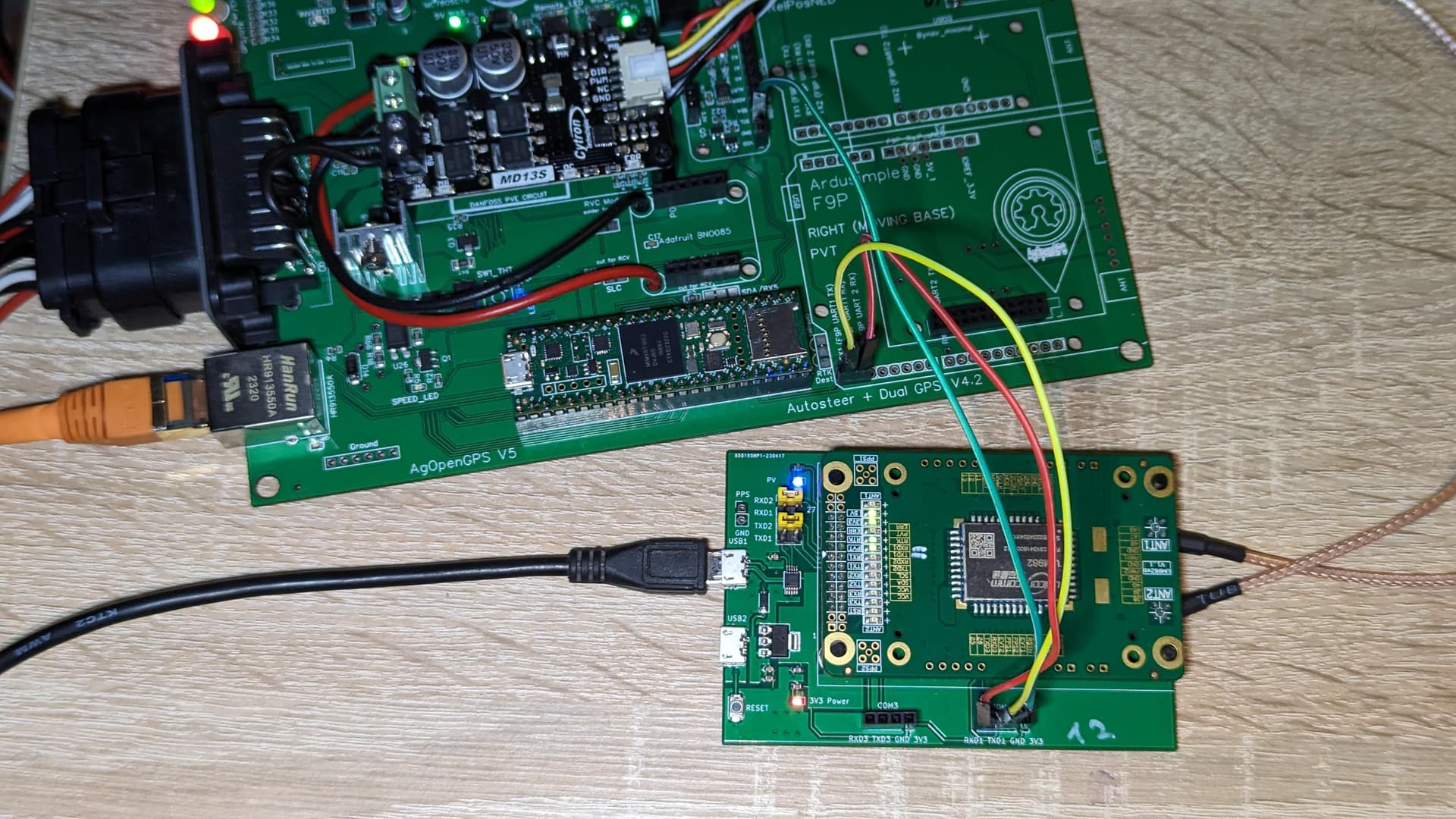
I edited my previous answer. I did a cursory look at the schematic and my original post was in error.
If that’s true, the Dual BayNav c1-fd wouldn’t work on the AIO board 4.2 either, it has the same pinout as the UM982. It also has TX on pin 15.
Is the bynav routing correct on the v2.4 PCBs?
You mean v2.4 All In One Standard? The main folder in the repo says V2.5. The gerber, bom and pnp files say 2.4. If so IDK since the repo only has the EasyEDA files for the AIO Micro board.
Yes, has the bynav pinout changed from it to the v4.x?