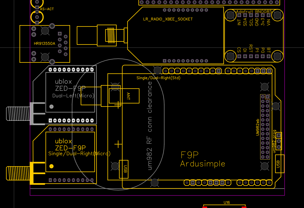
I don’t know. The V2.4 folder only has the EasyEDA file for the Micro board not the Standard board. The Standard board is the one with the Bynav socket.
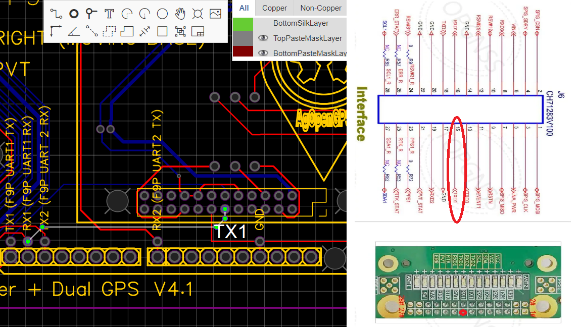
Bynav socket (um982) TX1 is connected to RX1 of F9P, which is connected to teensy serial 7 TX (29) pin.
So it seams wrong.
1 Like
Thanks. I was seeing the same thing. Is it OK if I add your picture to the issue with attribution of course?
I have an updated schematic, PCB and Gerber that I will commit to the boards repo for the admins to check and hopefully update the files in the repo.
1 Like
Yes, of course.
This affect use of bynav as well. It seams no one used it, if this was not discovered till now.
So good proposal for future boards is to make bynav slot um982 slot. As there is much higher interest in it then bynav. So leds on pcb and other um982 uarts can be used.
2 Likes
Thanks @Radmuffins @chri5k for digging into this. Can anyone confirm this with an actual module test? Sometimes the labels for TX/RX are from the module’s perspective and sometimes it’s from the other device’s perspective so it can be tricky to know for sure with a real test.
1 Like
@tomischmid noticed the issue when he plugged a UM982 board into the Bynav slot. A picture of his setup is a few posts up from this one. All of the UM982 boards I have use pin 15 for TX and 16 for RX. I have confirmed this when I connect them to a USB to TTL converter. I have to connect pin 15 TX from the UM982 board to RX on the USB-TTL and pin 16 RX from the UM982 board to TX on the USB-TTL. Reversing the wires (TX->TX and RX->RX) between the UM982 and the USB-TTL results in no data. It seems between tomischmid and these tests the schematic and board are incorrect.
Here is the link to the issue on the boards repo.
I have found the below vendor on Aliexpress to be quite good. I have ordered 3 boards from them on three separate occasions. All were shipped within 24 hours and arrived in the US in 9 - 10 calendar days via Aliexpress Premium shipping ($4.11 shipping). I have had other vendors take 3 - 5 days to ship, not ship at all, message me about raising the price, etc.
Aliexpress link weirdness. The price shown below is for the antenna even though the picture is the board. The board is currently $120USD.
2 Likes
I also ordered 2 from them, very good communication. Fair price (lowest normal price for me), they have good price on 3band antennas as well.
60 euro… not bad oww wait thats only antenna
Wouldn’t the KSXT message be the message of choice? Page 256 of the Unicore Reference Command Manual describes the KSXT message. This seems to me to be identical to the KSXT message from the bynav receiver (possibly differences in field IDs 21-23). I have a Bynav running that only outputs the KSXT directly to the tablet via USB, AOG works wonderfully with it. (I have no idea whether the AGIO firmware can handle this and would loop the message through.) Has anyone tried the KSXT message from the UM982? Avoiding such a conversion into an NED vector seems desirable to me.
I too have bynav and um982. I have used ksxt from um982 just like bynav. It works with Tony’s canbus ino in forwarding mode. I don’t think the roll of the um982 is as good as bynav. I feel it has some filtering/smoothing on the roll compared to bynav. I need to look into um982 settings more to see if there is something that affects this.
Also um982 ksxt is missing the correction age.
The aio ino will not pass the ksxt data to udp as I have tried. It will need some changes to make it work.
KSXT would be an ideal message except the UM982 does not output roll information directly. Any message that has the roll field will always show 0.00 for roll. I checked with Unicore and the roll field is for future use with an IMU. No information on what IMU or when IMU integration might happen.
The KSXT message is in the same format as NMEA and the NMEA parser in AOG will handle it. The code just needs the appropriate NMEA handler added to parse the sentence and put the data in the correct PAOGI fields.
To calculate roll, the formula needs the difference in height between the master and slave antenna as well as the baseline length between the two antennas. A combination of BESTNAVXYZ(H) and UNIHEADING messages have the required information. BESTNAVXYX(H) has the height data and UNIHEADING has the baseline information with appropriate precision.
What boards are folks using with the Bynav or UM982? Recently it was discovered the AIO v.41 STD has the TX/RX pins reversed on the Bynav slot so the UM982 or the Bynav can not pass data to the Teensy. The AOG devs are looking at updating the AIO STD board but no ETA at this moment.
As we put our Antennas across the vehicle the pitch data in ksxt is what aog reads as roll. I believe this is also the case for gptra and ptnlavr from trimble.
As for boards. I have my own design that takes the bynav for use with canbus steering.
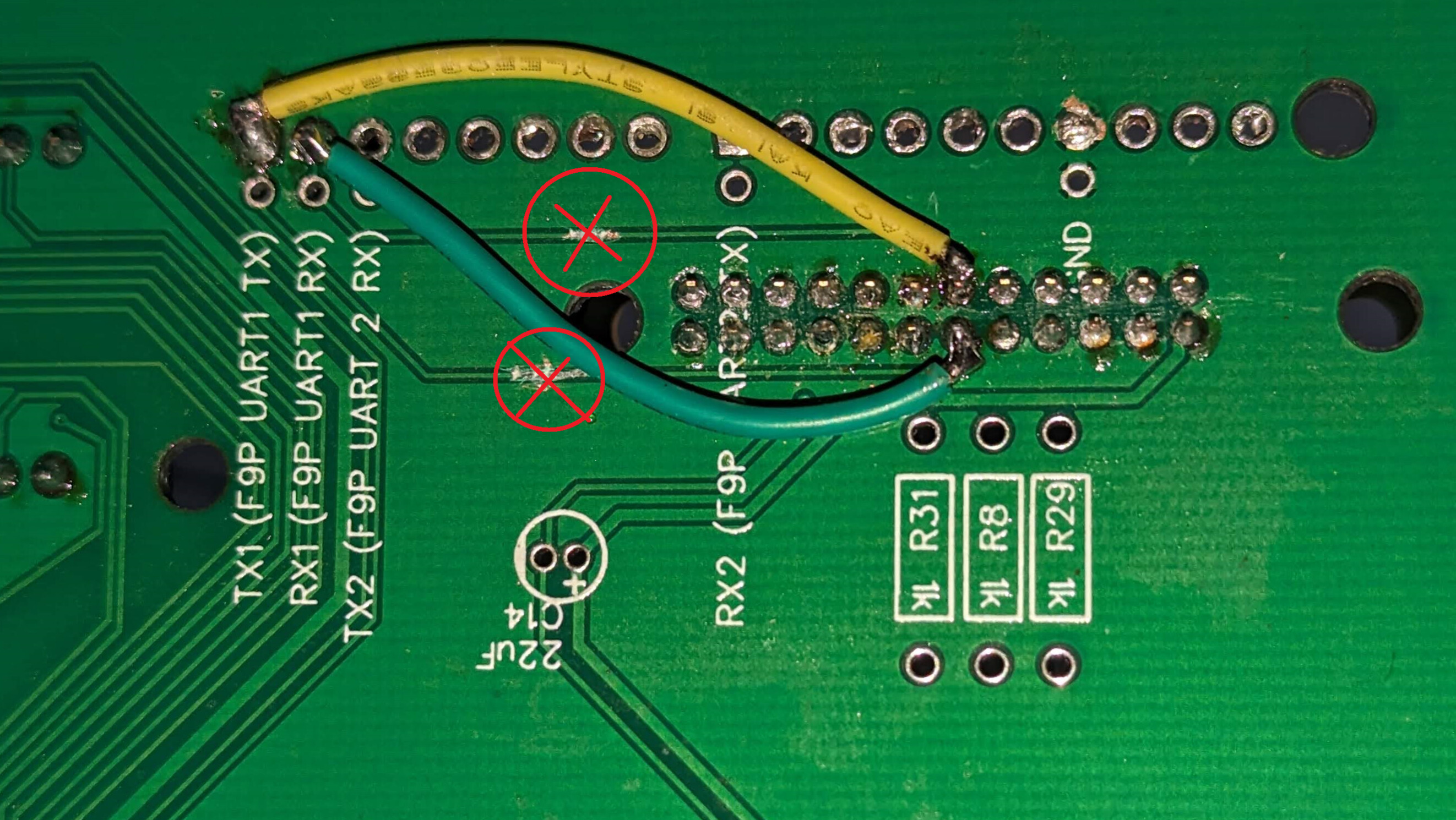
You can easily convert the existing AIO board to use the UM982. The two existing conductor tracks must be cut. And then two solder bridges are added
2 Likes
Yes, this is what we did for roll, got pitch from TRA.
Roll/pitch, heading needs to be compared to IMU, one possibility is use um982 for heading, IMU for roll.
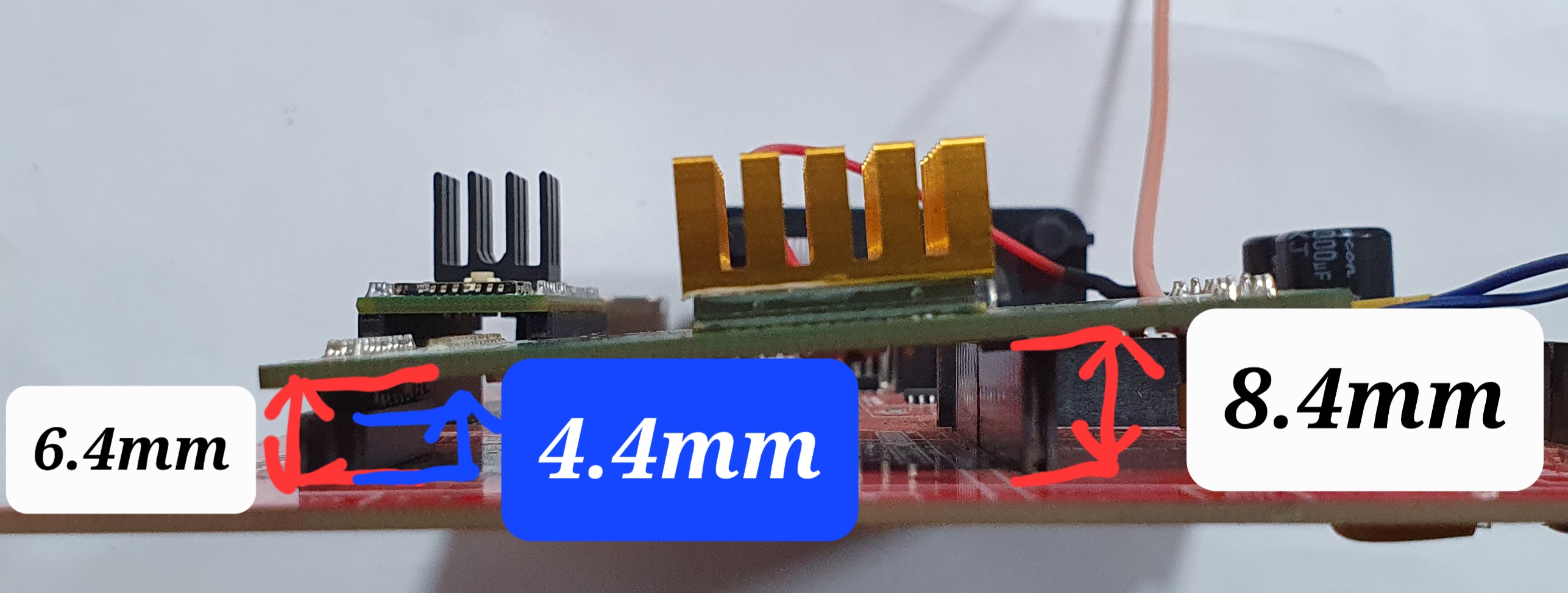
How tall is the socket/header on the pcb for the um982? As tall as the Std F9P sockets or shorter like the Micro F9P sockets? I’m wondering what components can be placed on the PCB underneath the UM982.
2mm heders are 6mm, 2.54mm 10mm height mesured with pcb, or 4.4 and 8.4mm is height of plastic parts alone.
So with F9P headers on pcb um982 needs taller headers.
Updated my first post with the latest Command Reference manual and newly released Evaluation Board manual.
Here is the list of changes to the Command Manual.
Extend SIGNALGROUP and SBAS configurations
Add some configurations, including CONFIG EVENT2,
CONFIG RTCMCLOCKOFFSET, CONFIG PVTALG and
CONFIG PSRPOSBIAS
Add some logs, including QZSSEPH, GPHPD and
PPSSTATUS
RTKSTATUS: update the description of field 17
BD3EPH: update the description of IODC and IODE
Table 7-54: update the ID number of IRNSS
Table 7-86: update the description of Bit3
Update the optional parameters of the MASK command
Table 3-8: change the name of UAV “FORMATION” mode to UAV “HIGHDYN” mode