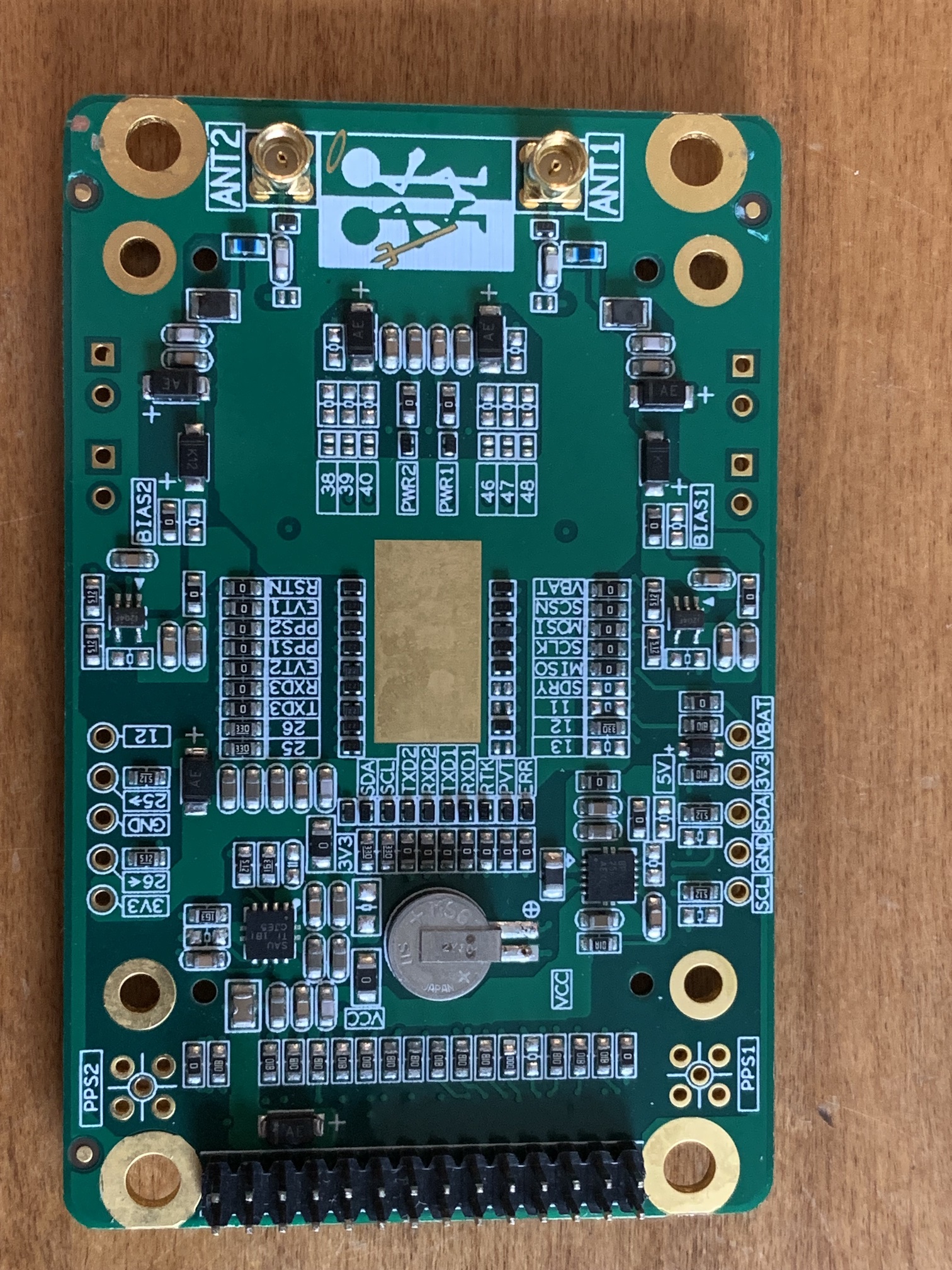
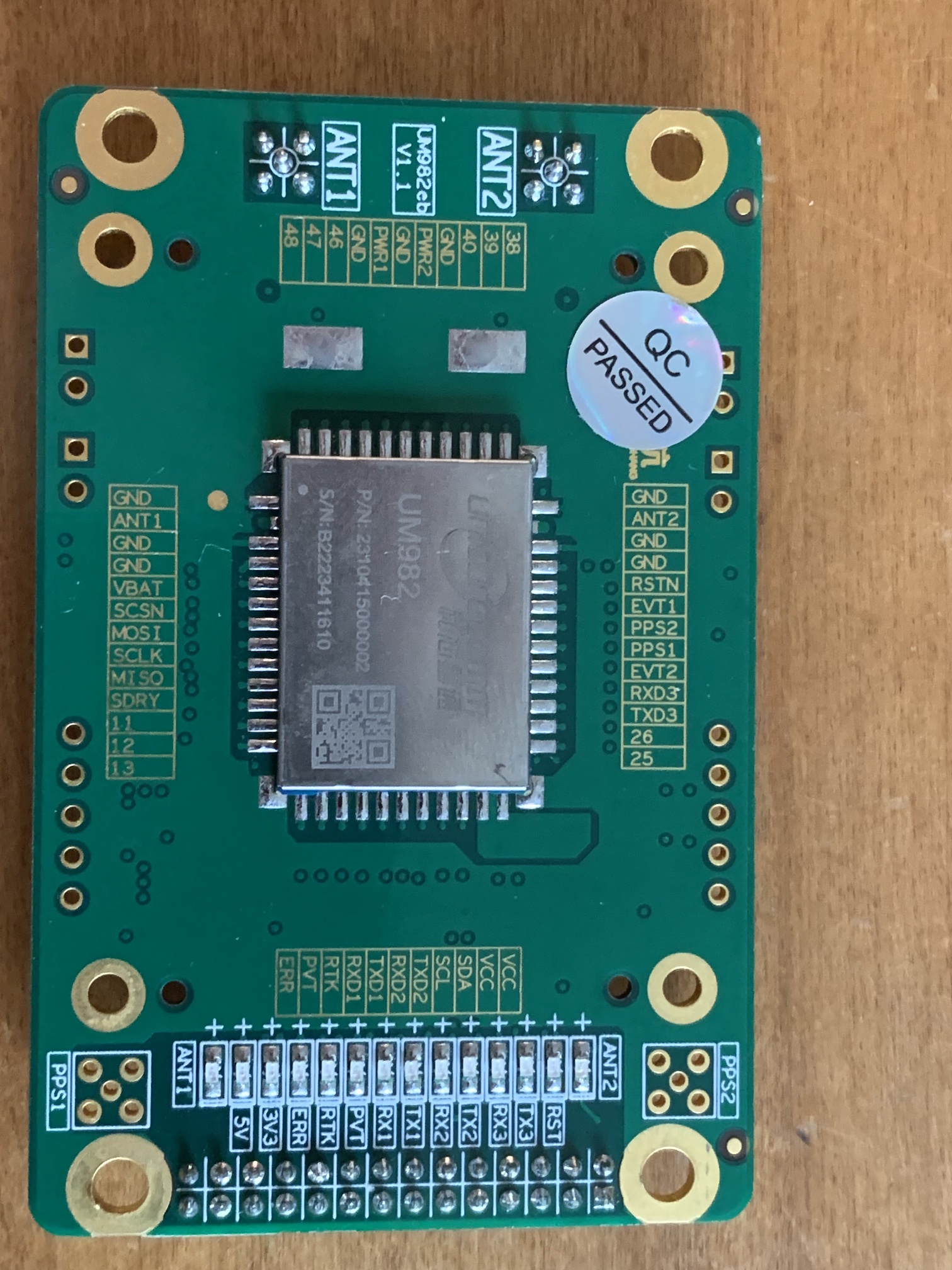
@m_elias, The latest version of the UM982 board I received has all 28 pins on the header.
FYI: the PCB can handle more amps than the ampseal connector can ![]() no need to add those extra cables to cytron (and now we have a 20A ampmeter so you could measure how much power your motor needs)
no need to add those extra cables to cytron (and now we have a 20A ampmeter so you could measure how much power your motor needs)
I guess we better put the full 28 pin header on the pcb. JLCPCB doesn’t seems to have any thru hole 2mm headers that I can find so smt it is.
Not much for inventory though. So, leave it thru hole and self solder if needed?
I think leaving them through hole will be fine. Mouser, Digikey etc have stock for the 2x28 2mm. Easy enough to self solder.
Watch the JLC PCB routing. First time it routed the trace between the holes crossing from one side of the connector to the other. During plating, it created a short that was not caught in QC. I used open router on the next board and it did not route the trace between holes.
Through hole is better, easy to find 2mm headers on aliexpress or other sites.
I don’t quite follow, can you show a picture to illustrate?

The PCB in EasyEDA showed the trace coming from pin 13 going between pins 12 and 14. The manufactured board shorts pin 13 to 14.
This was not the AIO board. It is one I designed but I wanted to point out the EasyEDA router does sometimes have issues routing traces with dual row 2mm headers like the one used by the UM982.
1 Like
The traces don’t look “centered” between the holes for some of the other ones too, did you use an autorouter feature? I always manually route the traces and tweak them, maybe a bit ocd on my part.
Yes, I used the EasyEDA auto router. I made a second board but used Open Router and it did not route traces between the pins on the connector. EasyEDA mentioned in their documentation that their router sometimes fails to route. They recommend exporting the DSN file and using Open Router then import the SES file back into EasyEDA.
Check the minimum trace to pad clearance in easy eda. It shouldn’t even let you place a trace like that unless you set it to ignore conflicts. Plus you should always check your traces manually as the auto router often doesn’t route traces as efficiently as they should be.
I looked at the PCB file in EasyEDA and those pins are not shorted. They are in the Gerber. Looks like some sort of registration error between the PCB file and the Gerber. I increased the minimum clearance setting and the router avoided those routes.
Thanks for the tips!
I have been testing the UM982 for quite a bit now. Here are a few observations;
-
Accuracy and stability appear as good as dual F9P when using dual band (L1/L2) antennas. Working on objective testing and data gathering once my L1/L2/L3 antennas arrive.
-
The UM982 needs a good power supply. With 2 antennas it draws ~425 mA steady state and about 700 mA during startup. This depends on the antenna LNA current draw. I used the Ublox ANN-MB. The Teensy or ESP 3.3v lines are not enough. Especially if they are powered by a USB port. They seemed to work initially but after a few hours, voltage drops caused errors and instability. Increasing the number of logs requested and the reporting frequency increases current draw. Once I got this and #4 below worked out, the UM982 has been running smoothly for 24 hours a day for about a week.
-
I have settled on GGA, VTG & HPR messages at 10Hz. Swapping pitch for roll by mounting the antennas perpendicular to the direction of travel as others have done. Putting a 90 degree heading offset on the UM982 config to compensate. This requires the fewest changes to the AOG firmware and still provides all the needed data. I have a modified version of the AOG firmware on my Github.
-
Not all MMCX to SMA cables are created equally. I bought one set from Amazon and the male MMCX plug was a sloppy fit into the UM982 female receptacle. This caused intermittent loss of signal / RTK Fix. An occasional short caused the board to reboot. The instability of this and power supply drove me nuts trying to track down.
-
Unicore seems to be releasing new / updated features about every six months. This a based on the frequency of command manual updates. 2022-10 initial release , 2023-05 update & 2023-11 update.
-
Applying a smoothing algorithm (moving 10 sample average) in the AOG firmware to the roll data helps keep the roll gauge jitters in AOG to a minimum.
4 Likes
This is what I was planning for vRegs on a v5 PCB:
5V1
-Teensy
-Canbus
-ACS
-Spd Pulse
-Btn Inputs
5V2
-Std F9P
-ESP32
-RTK Radio header
3V3
-F9P Micros
-Xbee
-RTK Radio header
-Bynav/UM982
but it sounds like running the Xbee on the same 3.3v as the UM982 might be too much. Could we use only one 5V reg instead of two and then go with two 3.3v?
Um982 can work from 5v.
But I don’t think the Bynav can which shares the same header
Like on AiO 4.x STD, 5v direct jumper cable or put Vreg for bynav.
1 Like
Have you tried it at 5 volts? I know the UM982 chip itself is 3.3v and there is an onboard 3.3v LDO regulator. I have not been brave enough to try 5v on the Vcc input pin.
I use it at 5 v.
Yes, my um982 never worked from 3.3v, only from 5v.
Dont be brave enough to try 5v on rx tx pins.
Thanks Gruni and Radmuffins. I’ll try 5v Vcc but not on the LVTTL. ![]()