bonjour
je débute je suis au début de mon pcb je voulais savoir si il faut absolument des sockets pour les 4n33 ou peut on les souder directement ?
merci
They are not necessary, but there are fakes on the market, they are easy to replace if they fail, so there is not too much heat when soldering.
Ils ne sont pas nécessaires, mais il existe des contrefaçons sur le marché, ils sont faciles à remplacer en cas de défaillance, il n’y a donc pas trop de chaleur lors de la soudure.
Hi! The BOM file you made for the kaupoimod v4.1 essentially includes all parts list from kaupoiv4.1 pcb? Thanks.
Hi m_elias about to order from JLCPCB and will use their pcb assembly using the bom and cpl you provided. If able, can you take a look if everything is in order. Thanks.
It’s been a while but I don’t see anything obviously wrong.
Hi m_elias,
Using the [lvmod210824_smd-leds_mostly-fixed_gerber.zip.pdf (kaupoimod v4.1 mod210727) and the accompanying [lvmod210824_smd-leds_mostly-fixed_top_bom.zip.pdf for the bill of materials and the component placement list, I availed of jlcpcb pcb assembly services. I now have 5 boards from JLCPCB and would like to check which of the bill of materials were actually soldered. I generated an xy graph of the CPL, adjust the size to be the same as the pcb and superimposed it to the mod210727 pcb. The result is shown below, I can’t seem to figure out which component is represented by the blue dots (middle coordinate) on the pcb! I assume, the coordinate system of the cpl is 0 for the left and bottom-most portion of the xy graph. Can you assist in figuring out the midpoints contained in the CPL corresponding to which specific section of the pcb? Made an example by pointing to the QWIIC coordinate of 66.04, 24.04 (blue dot) and indicated if that should be located between the QWIIC indicated on the PCB. Thx
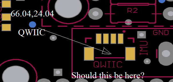

I ordered this board with SMD once but without the QWIIC connector. All component were at the right place. In your picture you can see that all blue dots are at some distance from the component.
An engineer will cheeck the file anyway.
No the 0,0 can be anywhere on the PCB, depending the editor used.
Hi Pat,
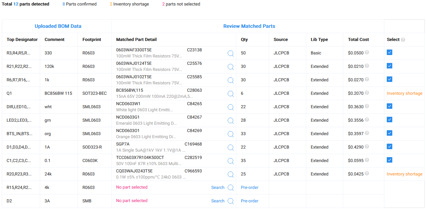
Thanks for the reply. I was able to figure out the the parts with specific coordinate on the pcb. It was not fun. Anyways, not all on the bill of materials were assembled by JLCPCB. The 3A diode, several 4K resistors, the trans PNP (Q), and 24K resistors. If able can you and others verify if the following are suitable parts to purchase and solder into the PCB.
- 3A diode - https://www.digikey.ph/en/products/detail/onsemi/1N5401G/1485525
- 4K resistors - https://www.digikey.ph/en/products/detail/vishay-dale/CRCW08054K00FKTA/5075408
- Q - https://www.digikey.ph/en/products/detail/nexperia-usa-inc/BC856BW-115/1232324
- 24K resistors - https://www.digikey.ph/en/products/detail/yageo/AC1206FR-0724KL/5897394
Essentially, I assume the lower the % tolerance the better but I am not sure when it comes to watt ratings.
Any assistance will be much appreciated.
By looking at the pdf file (schematics for the smd , found in same post far above) there are 3 4K resistors at the left. They seem to only be needed if you get the GY type of IMU. I don’t think 25 K resistor is essential either. I have not looked for the transistor, but have a look yorself.
The only transistor I know of is the mosfet, to drive the 6/2 valve. The name and sizes of resistors etc. are written in the pdf.
for 4k and 24k resistor you can use about anything with the correct resistance and footprint.
These are all for LEDs, optional but nice to have.
Q1 is for the led brightness according to WAS voltage (optional)
3A diode is correct.
Pat and Larsvest thx for the reply.
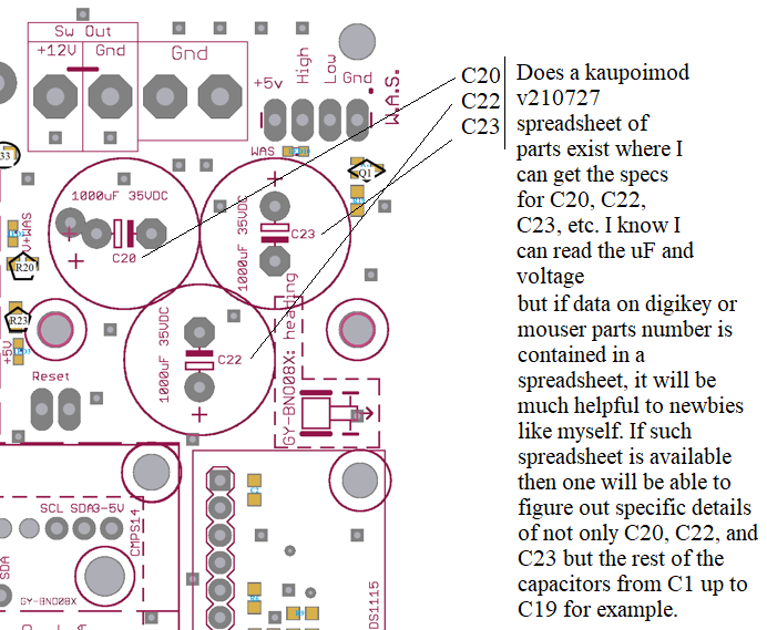
kaupoimod v210727 is different from kaupoimod v210419. The schematic below refers to the April version (2nd image) while the next image (3rd image) is the july version. There’s obviously a reconfiguration as placements of component do not corresponds. I have the july version printed so trying to focus on what the individual components are. Obviously there are mention of specific component which I think corresponds to a spreadsheet perhaps with the code. Example is reference to capacitors C20, C23 and C22 on the top right section near the WAS section (image 1. Do you guys have that spreadsheet? I know Larsvest indicated a pdf if one backs up in the thread but all I found is the april version not the july pcb that i have printed.
Assistance much appreciated.
Spreadsheet existence?
kaupoimod v7210727

kaupoimod v210419

In post 80 look for mod210824 , it is not a zip file.
Yes, check at post 80 for the SMD version, this is the one I used and is fully functional.
Got it thx
Hi Pat,
Looks like post 80 is more updated at august 24 vs what I have at july 17. Hopefully, not much difference. As you indicated you used the pcb design, did you assemble the board yourself? You also had the pcb assembled by JLC? By any chance you still have the bill of materials (parts list) spreadsheet?
Thanks.
Be sure to use the files on post 80.
All SMD where soldered by JLC. Through hole by me.
Here are the parts:
(no qwiiq and no 3a diode)
bom-1.xlsx (5,1 Ko)
note that I used some .125A diode instead the 1A due to shortage.
thanks
Hello
Does anyone have a 3D Model for CAD of the KaupoiMOD PCB ?
Maybe as STEP file ?
When I try to generate a 3D model out of the Files from OneDrive it does not work correctly…
hi, es there a Kaupoi card with ESP32 instead arduino?
Was there any update on this project?