Does anyone have picture of this PCB soldered with CMPS14? It isn’t used on example pictures. Also regarding placement when everything is ready, is CMPS14 required to be in certain position in the cab or can it calibrate itself?
Going to try my first ever soldering project this week.
I have now assembled PCB and it seems to be working! I am still waiting for drive motor but IMU and WAS are showing. How do you guys have attached mini usb on the arduino? I installed this PCB to aluminum box that was in the parts list and I can’t fit USB, connector is too long and it hits the wall.
I guess I will have to order one, I managed to fit normal one by destroying the plastics around it but it isn’t completely secure fit…
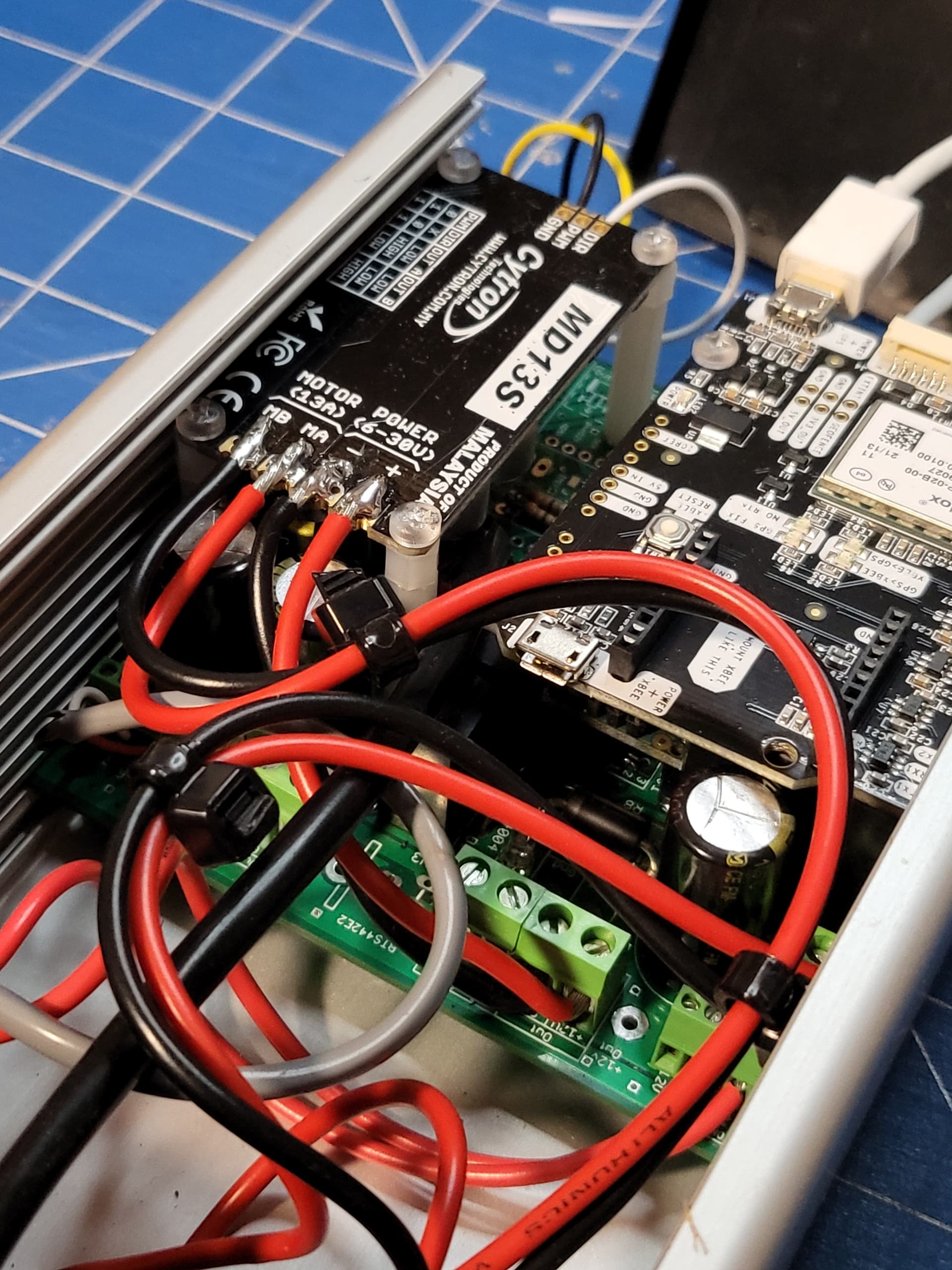
My box is bit different. I also had to change Cytrons place to fit PCB in heightwise, CMPS14 is under the board so Cytron didn’t have space to be so high up.
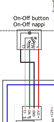
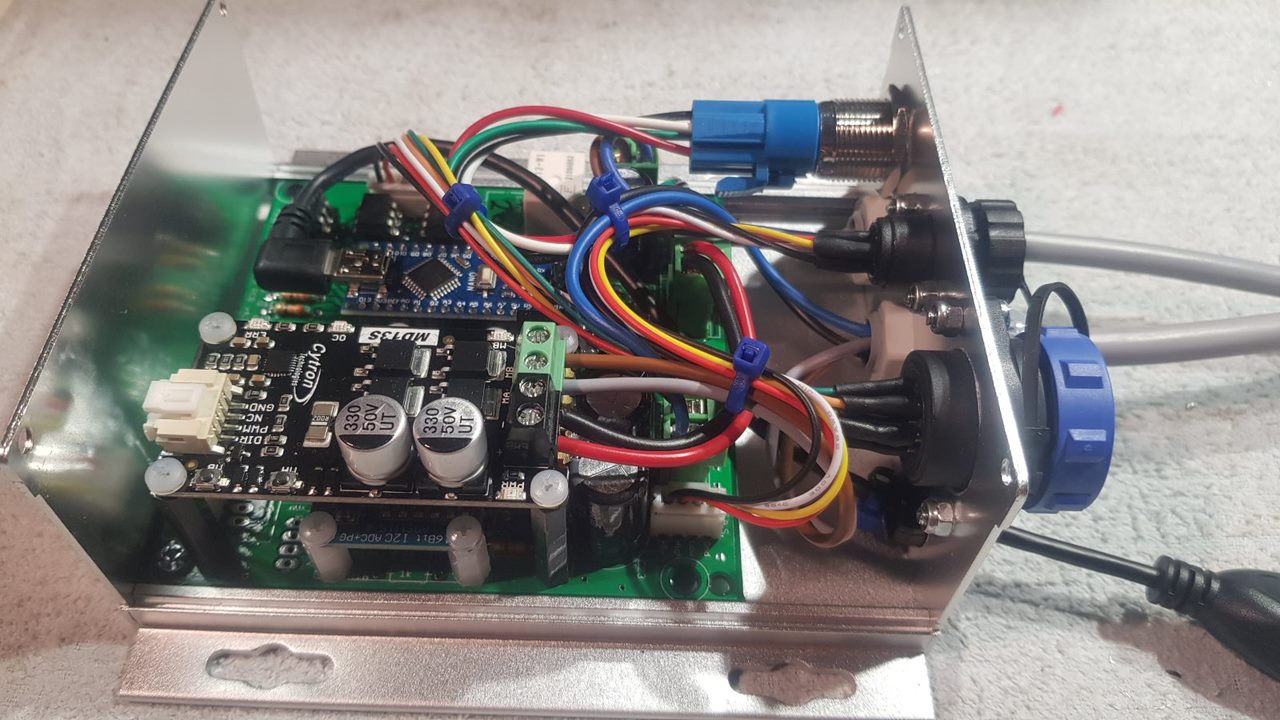
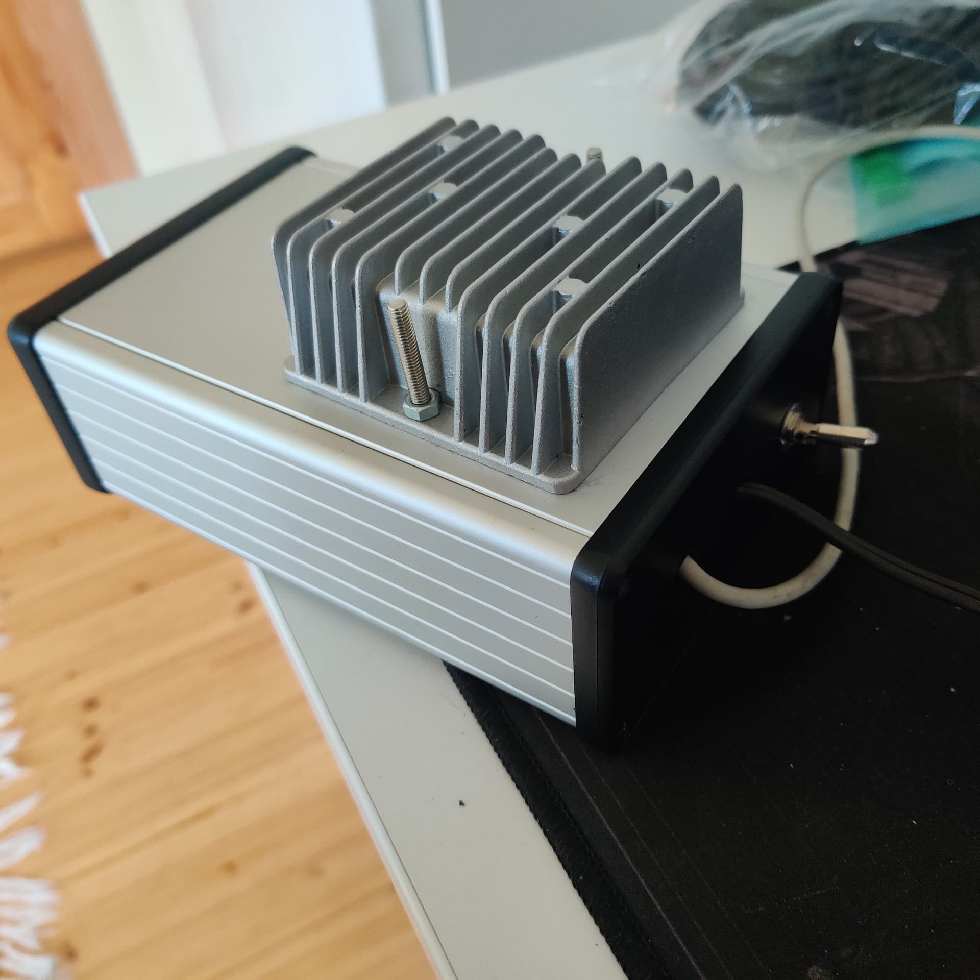
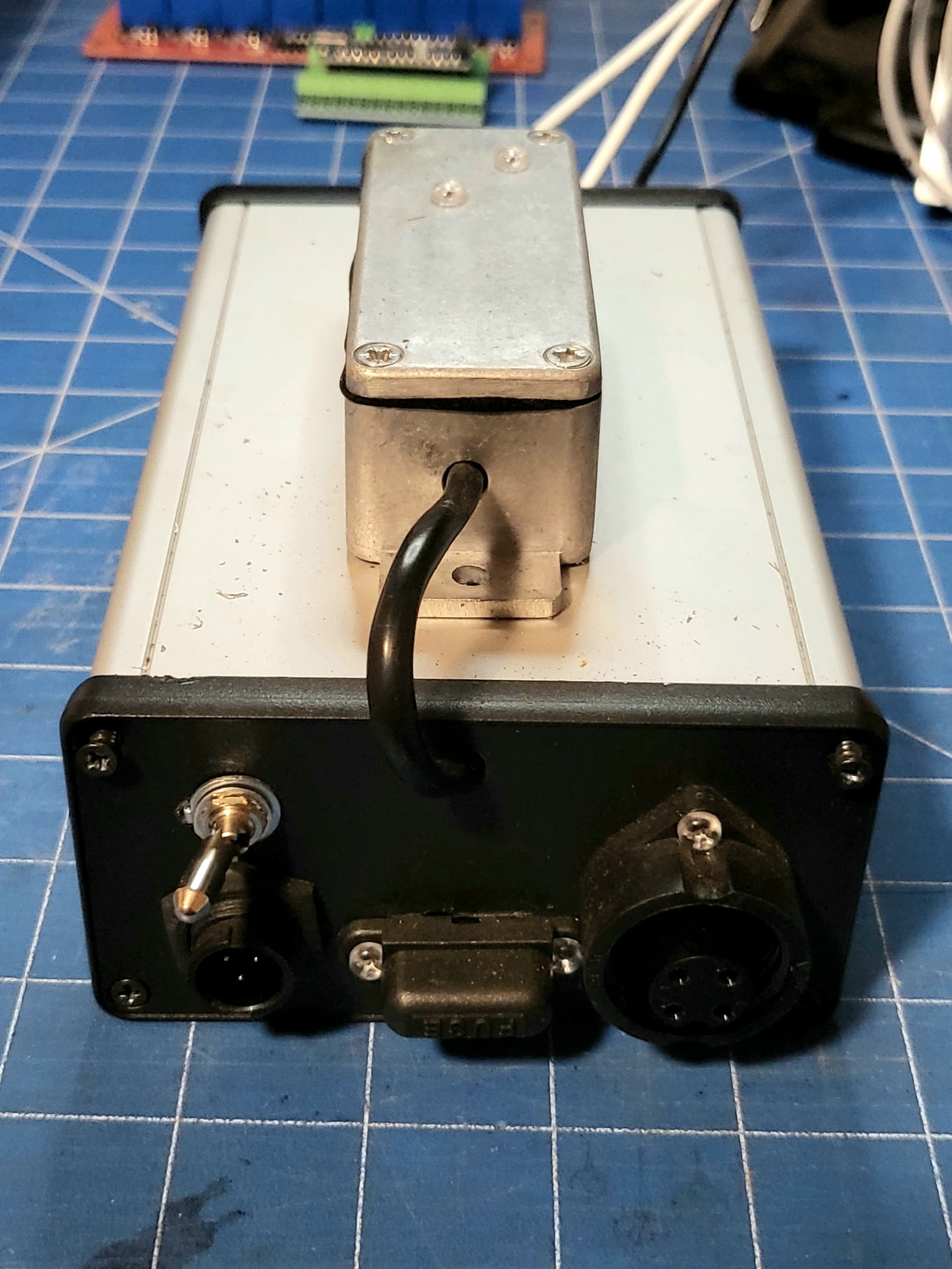
Looks good. I had the same problem with the cytron not fitting in the Hammond enclosure. I turned the cytron upside down and added some short hex standoffs on top of the existing ones. I also attached the CMPS via screw connectors and a short length of cable into an small external alloy enclosure (faraday cage) as I read several post reporting emf interference was making it unreliable. Limited work done, but seems to work well.
I think the reason the cytron didn’t fit may be because I had to substitute the big capacitors for another brand because of availability so physically they may be a little taller?
And I also put the f9p in the enclosure as well.
Tonight i’ll start pulling it all apart, I want to mount all the PCB’s on a sheet of acrylic plus another nano with an 8 channel relay board for sprayer control, and another relay board I have on order with digital and analogue inputs that has some nifty software with it. That should allow me to start and stop the tractor ,engage/disengage the hydrostatic transmission, receive alerts and monitor progress over teamviewer.
Hallo all,
I am new in the agopengps-Business and would like to thank everyone contributing to the project.
I am currently Sonderling my First pcb. I Chose the kaupoimod v4.1.
The wiring-diagram states a 47 Ohm resistor as R8. On the PCB itself engraved is R8 with 0 Ohm, which doesn‘t really make sense imho. The parts-list does Not include a 47 Ohm resistor.
Could someone here Support me regarding Thai topic? What kind of resistor is Needed as R8?