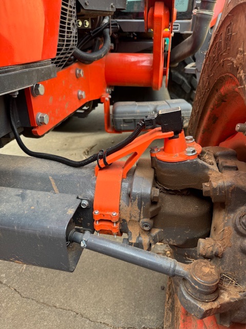
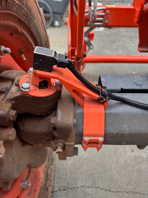
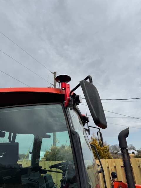
I used the AIO standard 4.5 along with a customized rate controller based on the RC-12 code. Two things that seemed to be working well that others might benefit from on other similar Kubota tractors is the wheel angle sensor mount and the antenna mount, which are both 3D printed.
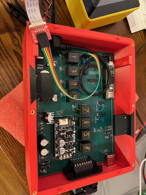
The AIO board is mounted along with power distribution and an Ethernet switch under the operator seat platform, so it is completely out of the way, but easily accessible by removing an access panel. I forgot to take pictures of this part.
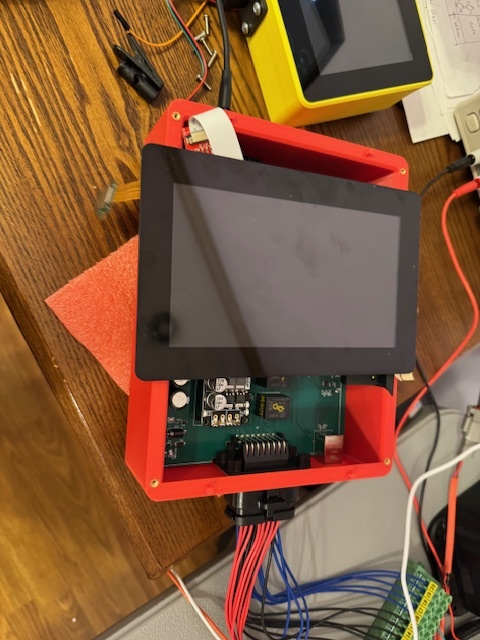
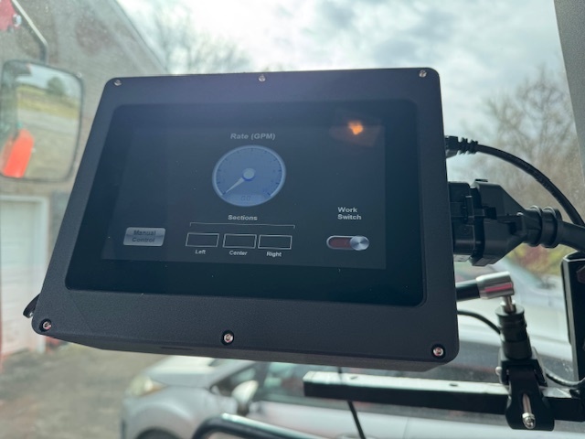
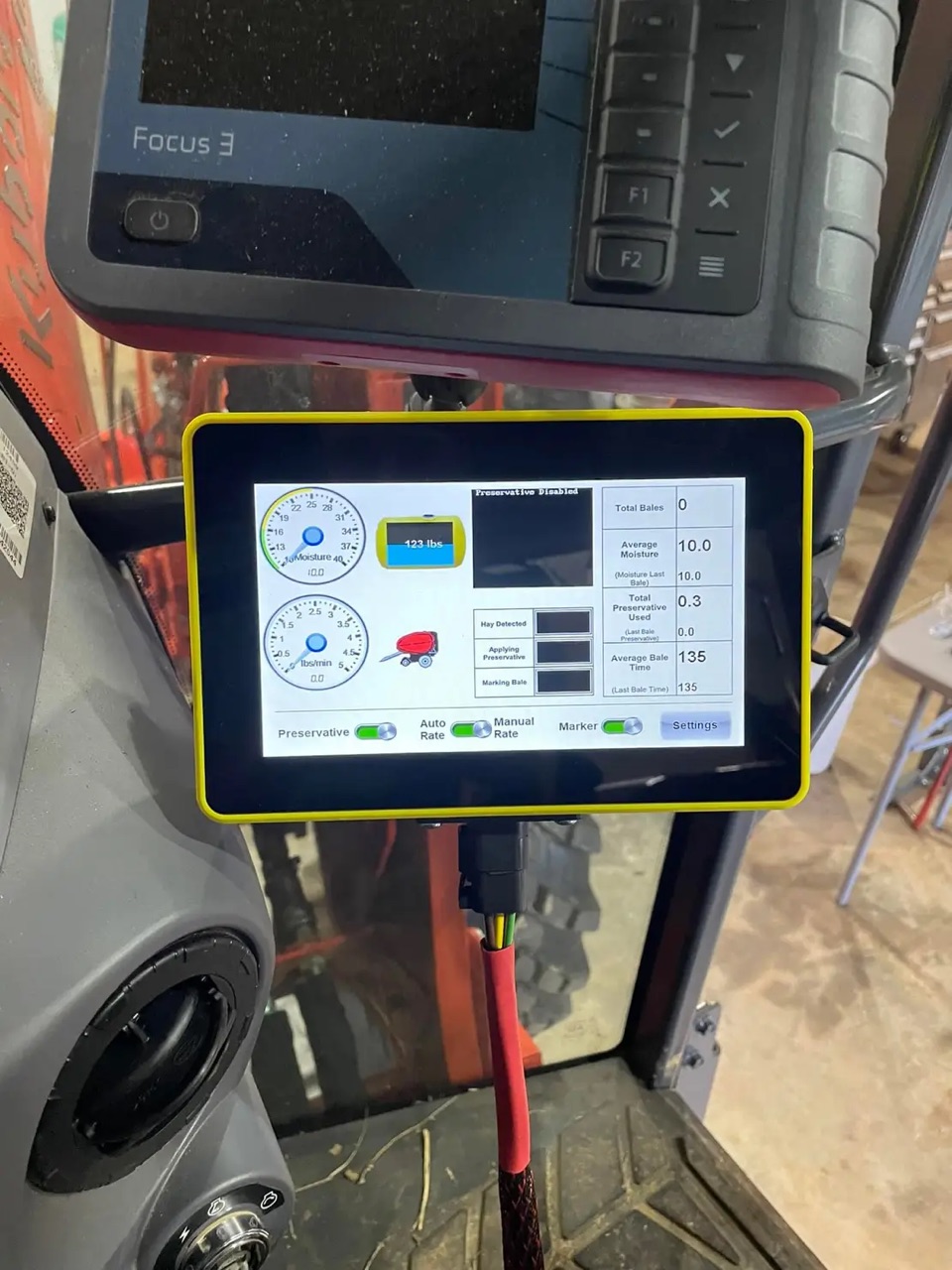
The rate controller was a mashup of things from the AIO boards, the RC-12 boards and a previous Arduino touchscreen hay preservative applicator project I had developed a couple years ago. I rolled the baler and sprayer features onto a single PCB and it runs modified RC-12 firmware spliced with custom firmware for hay baler functions (hay moisture and other sensors, preservative rate control, data logging, etc). The rate controller also allows a backup method (currently simple UPM and section control if in manual mode) of rate control for spraying, should there be a problem with the AIO board or agopengps.
I am planning to install a Baraki valve for steering in the next few weeks, but the whole system currently works great without it, so much better than my old onTrak GPS and Microtrak Spraymate II. Thanks to this community for making this possible!
Wow that baler interface makes me very envious.
I’ve got a good program for controlling rate and electric drive on my drill, but the interface is a 40x4 LCD and a million lines of code.
I’d love a professional looking interface like that.
Well done
I guess that’s what happens when you start going down the rabbit hole of adding “features” to your agricultural hobby. It has been a fun set of projects.
The AOG and rate control system have so much flexibility built in the possible uses are really broad.
The display I used is from a company called 4D Systems. They have a very simple GUI development environment that made it somewhat painless to create the interface. I’m not a GUI designer or even a professional programmer. I still spent a few hundred hours on the GUI and hardware/software integration with Arduino/Teensy, but now that I’ve gotten through that it would be very easy to quickly create whatever interface I need.
I’ve jumped on the 4d website and found they have an Australian distributor. Can you elaborate a bit on which display you chose and which of their software options you used to build the GUI?
I’m like you, not a programmer, but I like that 4d has a forum and looks like the right support is available for me to find my way through it.
I’ve used the capacitive touch and resistive touch versions of their “Gen4ULCD” displays based on their Diablo processor. I used the Visi-genie design tool, which is the easiest to use. Visi-genie is a what you see is what you get environment within their overall Workshop 4 IDE. I believe workshop 5 will retain the functionality but maybe rebranded it. They have arduino libraries that work well on the Teensy. My current display is a 7” capacitive touch wide viewing angle one with the cover lens bezel. They do offer a brighter display option, which might be better in sunlight, but I don’t know if it has as wide of a viewing angle. I definitely prefer capacitive touch in my application, as it seems more responsive. The cover lens bezel makes it very easy to bond with a 3D printed enclosure. I’ve mostly ordered directly with the company in Australia and they have been responsive.
The display itself can also be directly programmed as a microcontroller and has the capability for various inputs and outputs which depending on your application could remove the need for a Teensy or Arduino. I have not done this. In my case, I simply use it as a display and control it using their serial library from the Teensy.
I load the GUI onto an SD card and that uploads to the display memory on bootup if it is changed. That makes it so I don’t need to open the enclosure to make GUI changes. I use an SD card extension cable for this.
The display draws I think up to ~800 mA at 5V. The serial inputs are 5V tolerant but meant for 3.3v like Teensy.
One sticking point, you could get hung up on is the method to command display reset during boot up depends on which of their breakout boards you use to connect to the Teensy. One pin on the display needs to be pulled low to reset, but if you use their Arduino breakout board it is reversed (pull arduino pin high). In perusing their forum this is a common area that can trip people up.
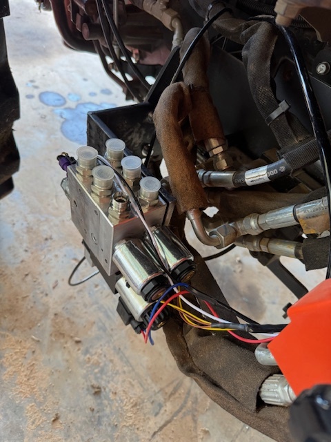
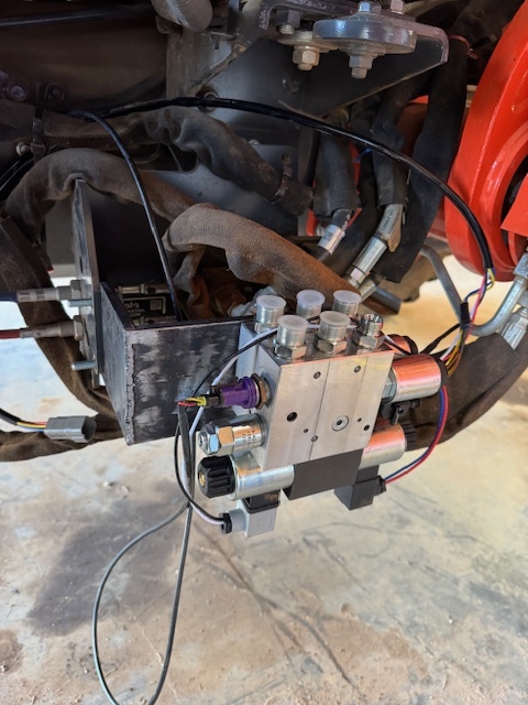
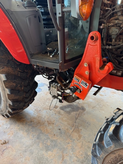
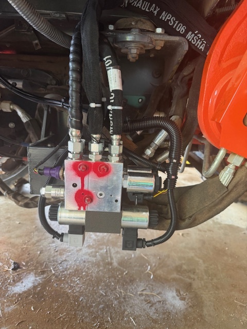
Here are some more pictures showing how I’ve mounted the Baraki valve. Some of it might also be applicable to similar Kubota tractors like the M7060.
The Baraki Valve is mounted under the cab next to the loader valves behind the brush shield. I made an L shaped bracket that bolts onto existing brush shield bolts. Don’t judge my welding too harshly…
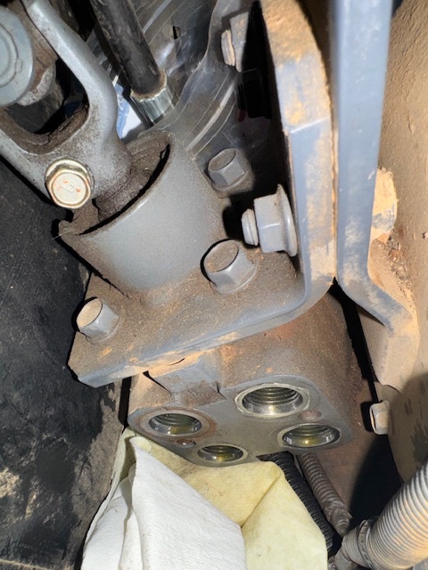
There was a 12mm steel pipe from the pump to the orbital that I replaced with hydraulic hose. The flange on the pump took a bit to find around here, but eventually I found some on eBay. This is what I found: