You do not need a voltage regulator.
The 5 V regulators doesn’t mind if it is 12 or 16 v coming in.
1 Like
Is this regular issue PCB v2 ? With phidgets 3269_3 with stall of 10.8A 24v its 20A on 12v too much for pcb or fuse will protect it?
you suggest something like this, this will solve above problem.
1 Like
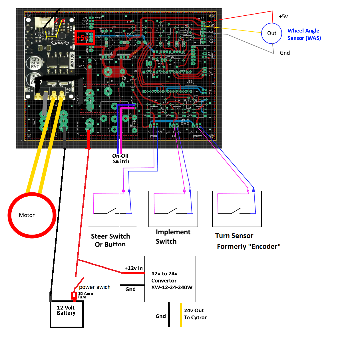
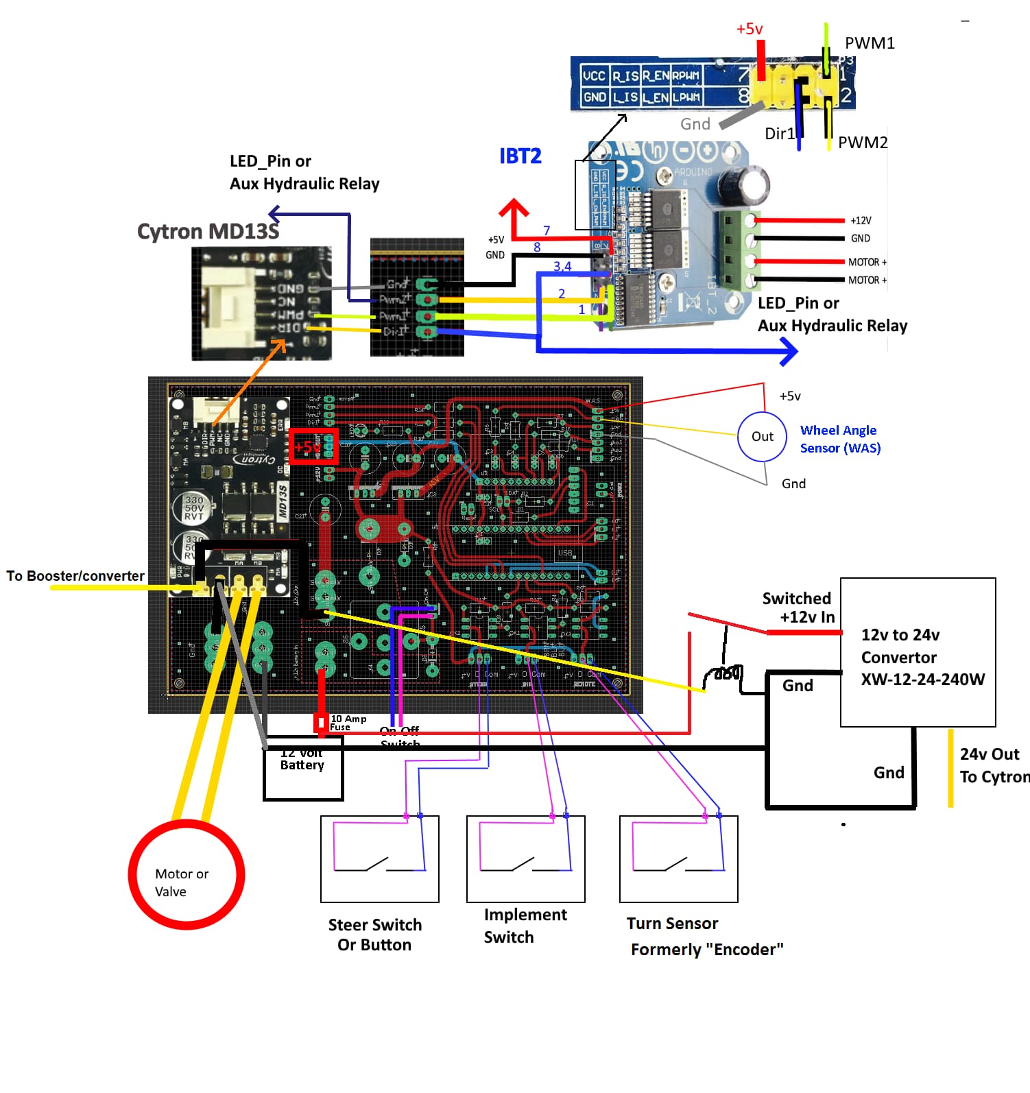
So a couple comments. I believe the relay on that PCB doesn’t not offer you any reverse polarity protection, the “On-Off Switch” can energize the relay coil regardless of your “12v Battery In” polarity. The 5V regulators are protected by the large diode but none of the “12V Out”. That being said the one diode by the relay does try to prevent the relay coil from energizing with reverse input power polarity until it burns off, after which the relay coil could energize. It would be best to add a series diode in wires going to the “On-Off Switch” blocking reverse voltage from trying to energize the relay.
If you still decide to use a relay on the PCB, then I would wire 12V direct to pcb and use the On-Off Switch as in your diagram to control PCB power. Otherwise, if you don’t use a PCB relay then put a good switch in series with the +12V to control PCB power.
Then use a switched “12V Out” from the PCB to control a 2nd relay for the Cytron or booster, which should have it’s own set of power wires from the battery, through this 2nd relay’s contacts.
+12V to +12V Battery in, PCB relay for power to pcb and short on off switch on pcb.
Can I go without second relay and use one 100A switch to cut power to pcb and converter after fuse as in my diagram?
I think so. In my combine my Cytron was directly wired to the battery, I left that way until end of the season. I also modified mine to allow free wheeling.
1 Like
I went to order my PCB and was short 2 components. I was able to source one of them, but I am having trouble finding C50984 or C5224030. Does anyone have any ideas on where to look for that part?
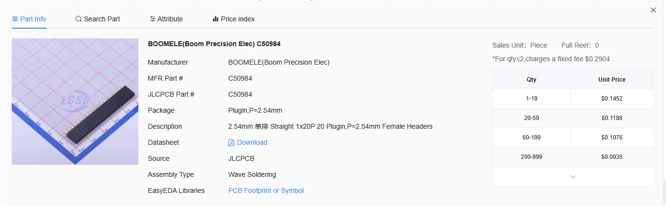
ebay or amazon. 2.54mm headers. You can get them longer than 20-pin, just cut to size. Makes a cleaner job than having JLC put that 20+4 pin mashed together
awesome thanks!
I ordered a whole pile of These from digikey.

I had the same email, I’ve received my PCB’s and can confirm they’re correct.
There are easy test strips Ground, 3.3V and 5V, so put 12V to Pin 22 and GND to pin 23 and check first.
Awesome thanks!
There also are green LEDs by each vReg that won’t light up if they’re reverse but it’s still a good idea to verify the correct voltage at the test points too.