So, not the most productive of days on the tractor. Arrived at my mates, and we fixed the antennas to the Case, and I started hacking his PCBv2 loom to fit the Ampseal/Micro. Not a huge effort, as I’d already done the power cables at home, so 5V (pin 1), WAS_H (pin2) and GND (pin4) to the WAS. Onto the hydraulic drivers, LEFT (pin 5) and RIGHT (pin 6) to them, with a common ground for the hydraulics going to pin 21 (GND).
Out to the field… ah crap, I forgot to wire up the SteerPin(8). We put a switch in line to the negative post on his tractor where we’ve plugged the power cables in, going to pin 8. Back to the shed, more ampseal fun, and once that was done…
Out to the field, noticed no RTK signal. Bit weird, was fine at home when the antennas were mostly shielded by house, but it’ll sort itself out, no worries. Opened a field, AB line… auto-steer… nothing. Hmmm… Perhaps legacy settings in my laptop or something, so started the Steer Wizard. Still nothing. WAS seemed OK tho. Damn, must have got wiring wrong, but I was really trying hard to do it right, so that would be embarassing…
Back to the shed. I had another board with me, that wasn’t stuck in the 3D printed case, so powered that up, and pressed MA/MB on the cytron. Nothing, no wheel movement! I knew from PCBv2 that they should have moved, so that wasn’t good. Multimeter out, pressed MA and tested MA on cytron to pin 4 (GND) on Ampseal - showing 12V. OK, so Cytron isn’t dead. MB also fine. But yet… when pressing MA, I wasn’t getting a voltage to pin 5, and when pressing MB, nothing on pin 6. So despite the cytron showing voltage and continuity testing showing my cable was fine, it wasn’t leaving the board???
So I was stuck… Telegram-time!
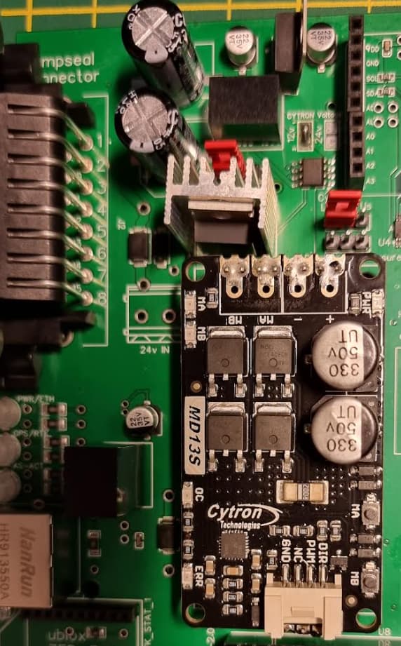
Jake kindly pointed to missing jumpers, at which point I checked the board again and noticed just above the cytron/heatsink, there’s wording to match the pin diagram - “Cytron Left or US” and “Right or Lock”. No worries, I have jumpers. It’s just that they’re 35 miles away ![]()
Dupont headers in the truck tho, so wired them up, pressed MA/MB and all good, steering again. Prised the other board out of the case, duponts onto them, all good. Back to the field!
This is what you want your board to look like and for the one obscured behind the heatsink, you want the two leftmost pins. BIG RED JUMPERS ALERT
EDIT: it was pointed out on the PCBv2 thread and in telegram that those jumpers are rated at 3 amps. In other words, I’m limited to 3A which is fine for hydraulics, but if you’re going to be driving a proper motor, essentially you now have a 3A fuse in the way. That’s not good… Refer to posts like these, of course everyone’s situation is different, you might NOT be wiring this way, but just keep it in mind:
If you’re unplugged, you should have continuity between MA and pin 5, and MB and pin 6. If you’re powered up, you’ll get 12V between MA or pin 5 to pin 4 when pressing the MA button on Cytron, and 12V from MB or pin 6 to pin 4 when pressing MB.
If you’re curious about what all that “LOCK” stuff means on the pinout, Jake replied:
Lock just sends 12v output from pwm2 when the steer is engaged. For 6/2 valve and Danfoss valves.
Back to the fields! Hmmm… still no RTK but we rolled around trying out the steering wizard for a good while. Couldn’t get the settings quite right, wondered if lack of RTK an issue.
Out with the command prompt, I could see a connection to rtk2go, so what’s the problem? Green center light on the board indicates an RTK fix, so… why isn’t AOG reporting RTK?
Chat on Telegram says “are you outputting NTRIP to port 2233” and netstat showed I wasn’t. I’d completely forgotten about the Position page in Ntrip Client Settings. So make sure yours is like this! UDP should be green, you’re very likely NOT using serial.
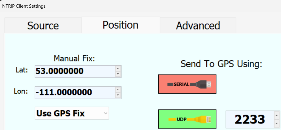
And just in case you didn’t know - no USB->AgIO on the new boards, UDP only.
At which point, my laptop battery ran out. (cries) So that was that. Be a good week until we get our next crack at it !
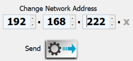
Some other things also came up today - before I left for the farm, I connected my laptop to my phone wifi, it pulled a 192.168.222.216 IP address. All fine and good, AgIO found the pre-programmed device on 192.168.1.xx that it been on my desktop earlier, so I did a “Change network address” and changed the 192.168.1 to 192.168.222. That sorted that!
I also plugged a LAN cable direct between laptop and Micro board. Now… I had crossover adapters with me just in case, but I knew that modern NICs will tend to sort themselves out if they detect a crossover situation, and mine did. But something still wasn’t right. UDP was green, but all devices were off:
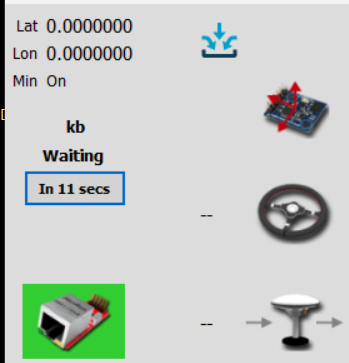
More pleas on Telegram, and I was helpfully reminded that of course I’d need to set an IP manually on the ethernet NIC on laptop (if you’re a tech type, that’s because there’s no DHCP supplied on that NIC, the wifi gets a proper IP because it gets one from the phone. There’s nobody on the NIC network handing out IPs).
The worst part here is I should have spotted that - and if I was at work, I’d have clocked it instantly - but it seems to be that when I’m having a problem with AOG, instead of applying my usual skills, I immediately assume I’ve done something wrong with AOG instead. I really need to sort that, it’s embarrassing I didn’t clock that.
Anyway, Start, Run, ncpa.cpl and bring up the ethernet NIC properties. Go into IPv4 set a static IP address for whatever you like (here, I’ve picked 192.168.222.20). Subnet mask will always be 255.255.255.0. In AOG, find the UDP modules and update with “Change network address” as above.
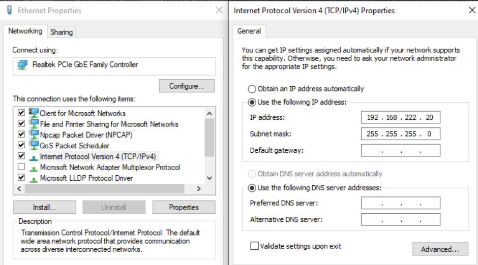
Do NOT set DNS or Default Gateway - those are only applicable on your wifi and if you set a default gateway on your NIC when your wifi has one, you’ll cause yourself problems. No need for DNS either.
If different operators have phones that hand out different wifi IP addresses, that won’t matter - your wifi connection will work fine on a different subnet to AOG. So pick an address for AOG, set it, and forget it.
Do remember tho that if you plug your tablet into a wired connection in the house, it likely won’t work unless you happen to pick the same subnet as your home - so you may like to change it back to “obtain an address automatically” if you’re unsure, when at home/office.
Also, the tool I’m using to crimp the ampseal pins - what a nightmare it was getting some of them into the plug so now although incredibly similar to the one I was using for other plugs, I don’t think it’s quite right. Do yourself a favour, make sure it’s exactly the right tool !
> Also-also… and this is a biggie - the middle light on the board being green does NOT mean “RTK fix”. If you have an RTK fix, it should actually be off. Yeah, I know that’s a bit backwards…
EDIT: I’m seeing COMMITs in the code base that look like this is now being handled in code, as opposed to following the ardusimple layout. So soon, green will indicate RTK fix.
That’s about it for today… progress, but a lot of time wasted on things I should really have sussed on the bench first !