AgOpenGPS
All in One PCB
Hardware
Vili
15 November 2022 12:39
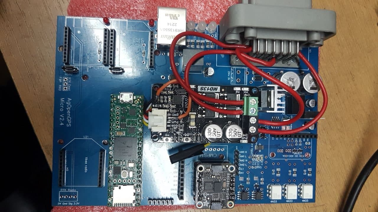
240
image
1280×720 128 KB
PWM2 to NC and Cytron wires
Micro Deustch
2 Likes
Micro v2.4 - a build thread
show post in topic