Micro v2.4 - a build thread

Before we start. Like all posts, this is point in time, and you might notice the dates are out of order now, because I’ve been editing things as new information has come to light, or there’s a better way of doing things. As such, don’t think of this as “if I follow this, it’ll all work out great”. Have a read and see how things are done in general. The team are trying to get some proper documentation going in the Wikis, for AOG itself and for the BOARD. So check them out too!

If you’re cool with the above, let’s proceed…

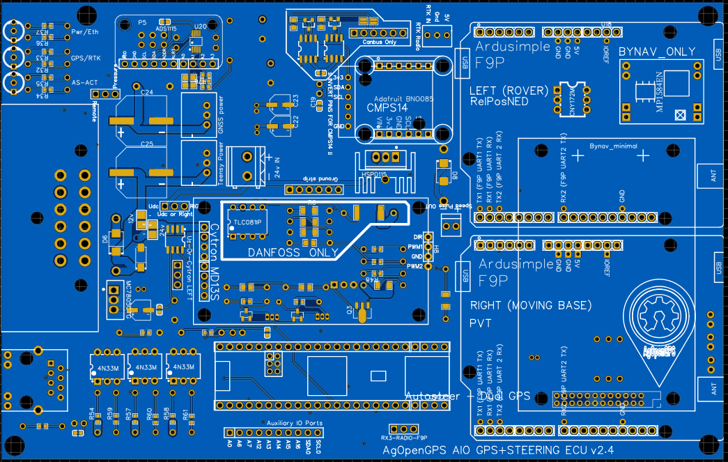
Thought I’d document my Micro v2.4 build as I work my way through it. Most of the things I’ve got stuck on, someone has already asked and answered elsewhere, so I thought a single thread I can put all my thoughts, process and mistakes(?) might be of some use.

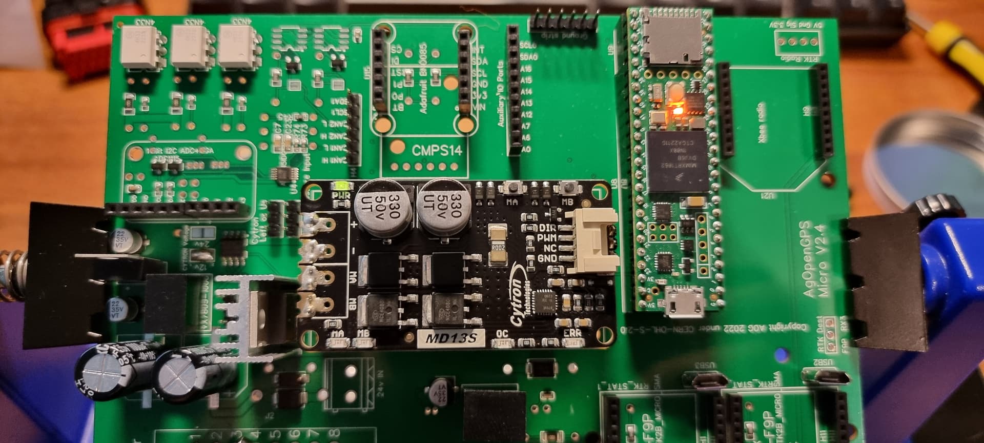
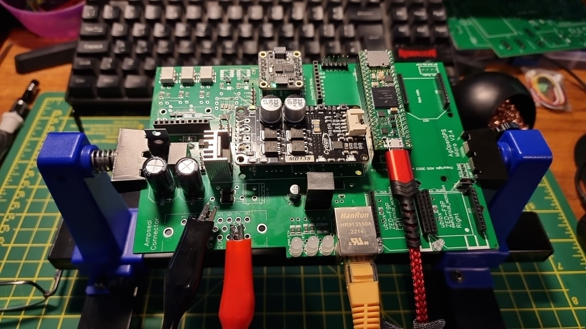
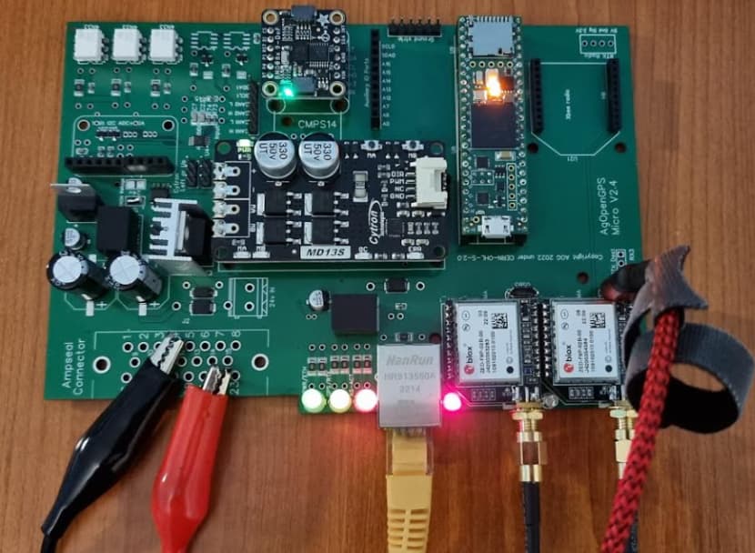
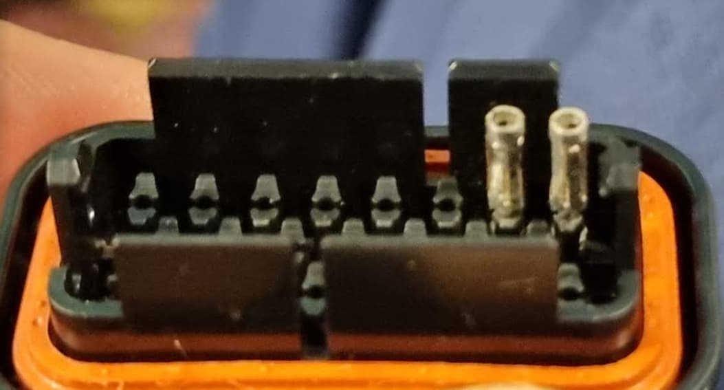
I got in early at JLCPCB and as such, I think I got pretty lucky with the components that it came with and as you can see, I went with 23-pin Ampseal connectors and Micro F9P.

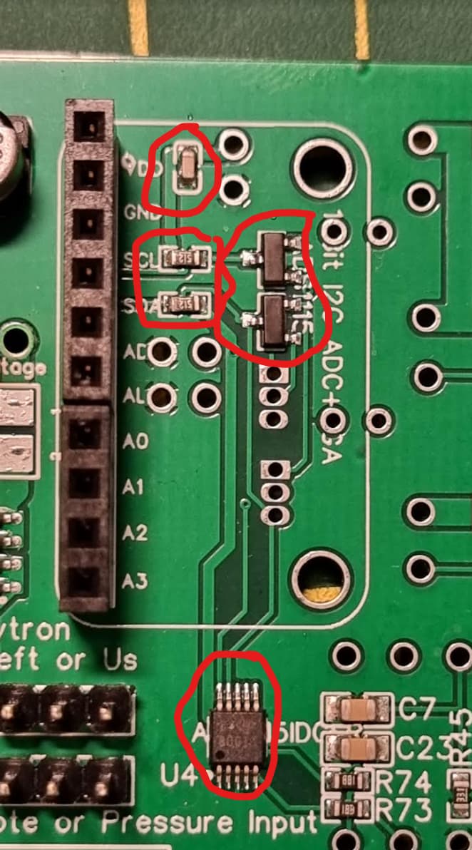
So, here’s what arrived. In my case, the critical parts that I thought I needed, highlighted in red, were missing. Checking the standard board reference images, there’s ring-fences for parts needed for CANBUS and Danfoss, not sure why they’re not marked on the Micro tho but thankfully the Telegram team advised I didn’t need them.

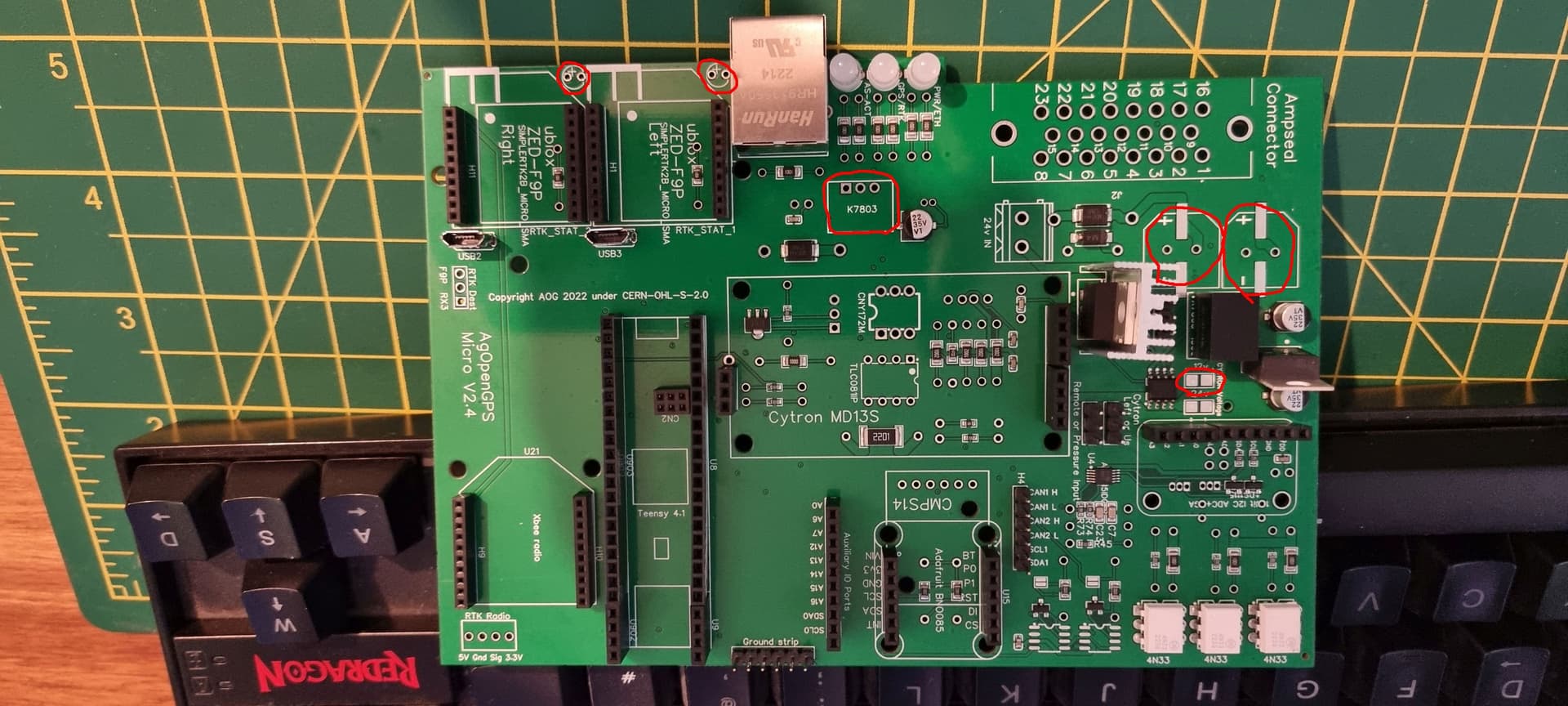
Those were 2x1000uf capacitors, the K7803 voltage regulator, and two little LEDs that I used from my previous PCBv2 stock. Also, as this is intended for a hydraulic valve tractor, and not to drive a motor, I soldered across the 12V bridge.

OK, and this just in - NEVER power up your board over 12V while the Teensy is connected over USB. See this page for why!! Note that in my pictures below, I’ve done that. This could have caused USB port damage on my PC. I got lucky - you might not. So don’t do it!!

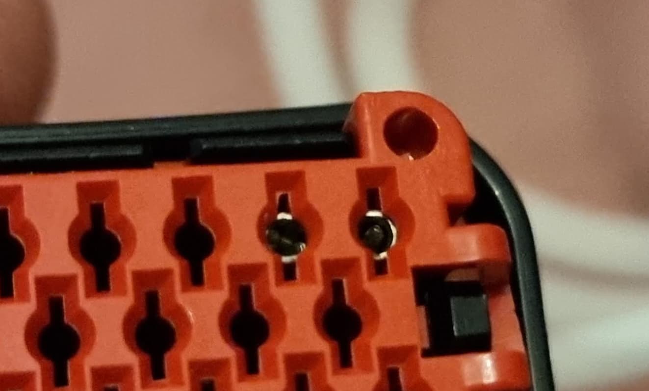
Then, onto the power-up sequence. I wanted to take things slow to watch out for the magic smoke. Checking the pin diagram for the Ampseal, pin 22 was 12V in, and 4, 21 and 23 were ground. I lightly turned some 3mm bolts in, performed some dark rituals, and connected up my power supply.

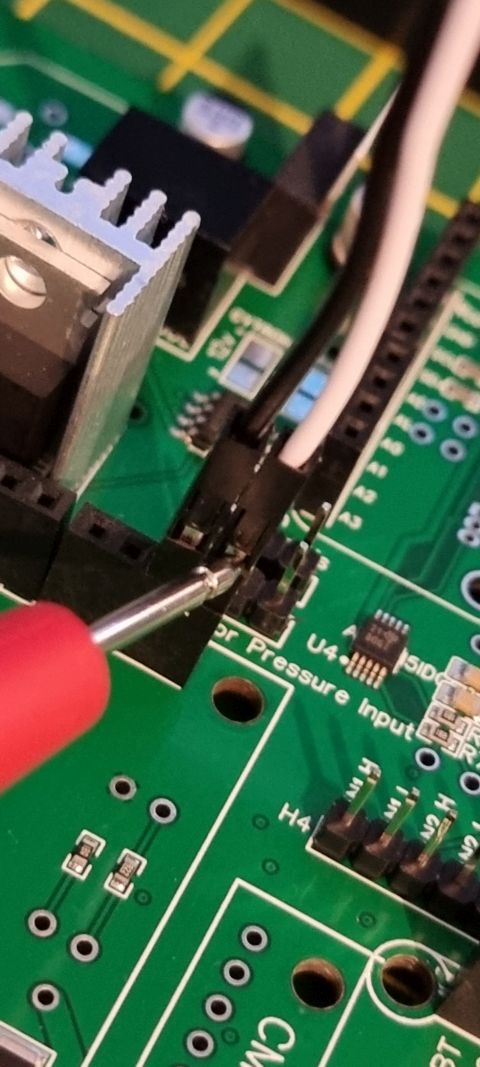
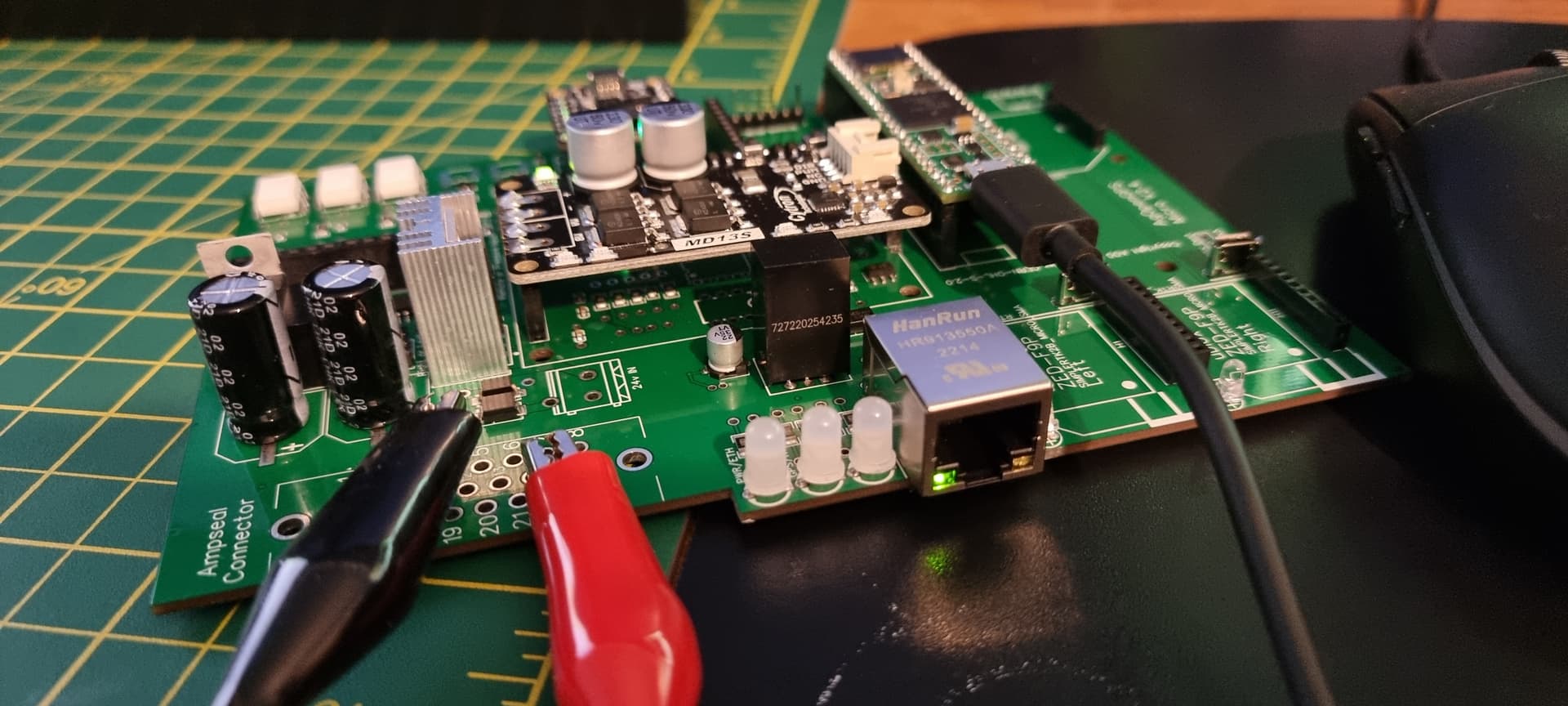
Gradually, I brought the voltage up, and no smoke. But no LEDs either… so I thought I’d press on anyway. I thought the best thing to check would be the Cytron input, as that should be 12V if all being well. I put some dupont wires in so I could connect my multimeter, and tested the two that provide the 12V sources, and they were good.

EDIT: Per jhmach’s instructions, NOW would be a GREAT time to test some critical voltages, before plugging any expensive stuff in. Don’t skip this step!!!

All in One PCB - #233 by Jhmach

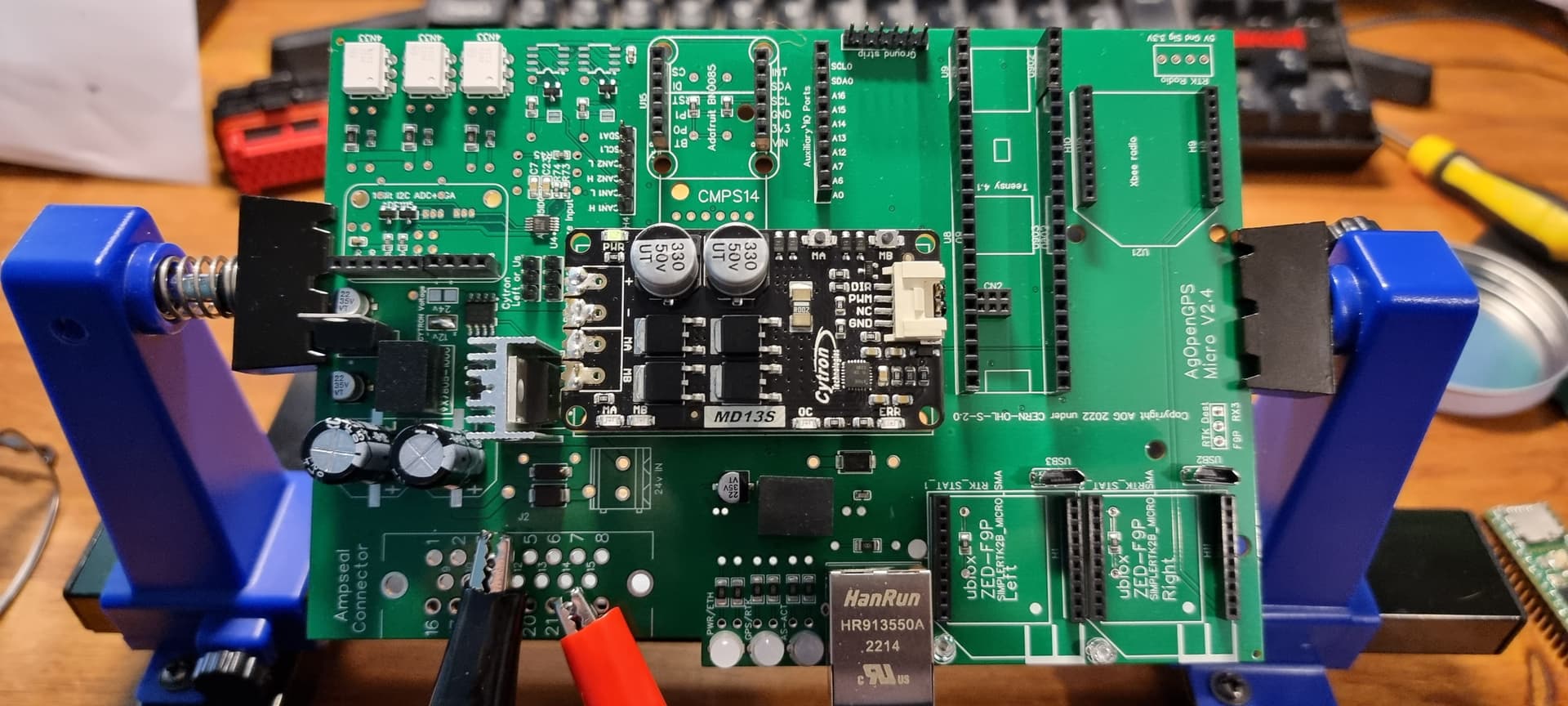
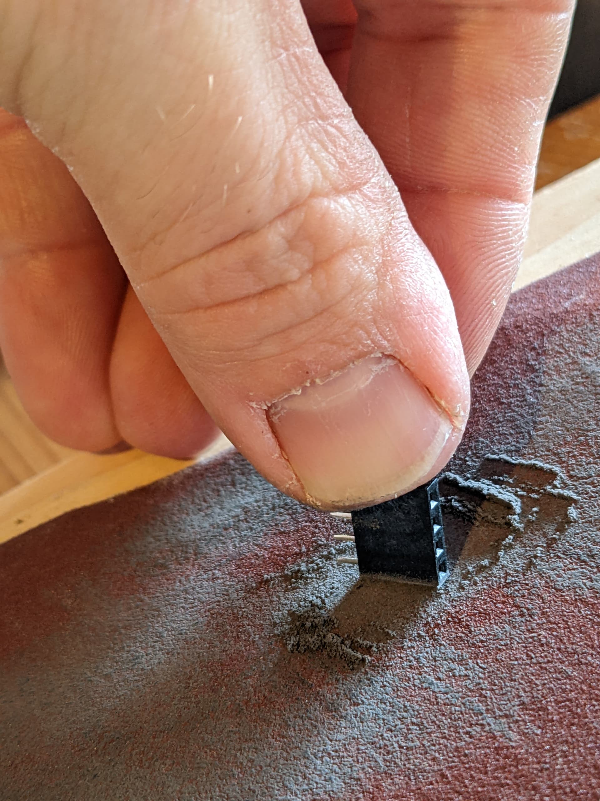
OK, time for some components then. Thought I’d start with the Cytron, which was a little difficult thanks to some bad header alignment from JLCPCB… placed an 8-pin header on the input side and a 3-pin on the control end. Because of how these fit, you actually solder the control end onto the edge of the PCB, not the holes underneath. Line them all up, do the control-end first as you don’t want the work at the other end making them impossible to align after. It’s not as tricky as you might think, steady hand and you’ll make a better job of it than I did.

NOTE: See warning on the top of page about not having board on 12V and Teensy on USB at the same time!

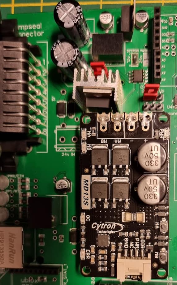
Back onto the power supply, and let’s bring it up slowly. At around 4V, the red “err” light came on on the Cytron, and around 7V it was all green continuing up to 12V. No problems!

I pressed the MA and MB buttons on the Teensy, and nothing died - the appropriate lights came on, so all good!

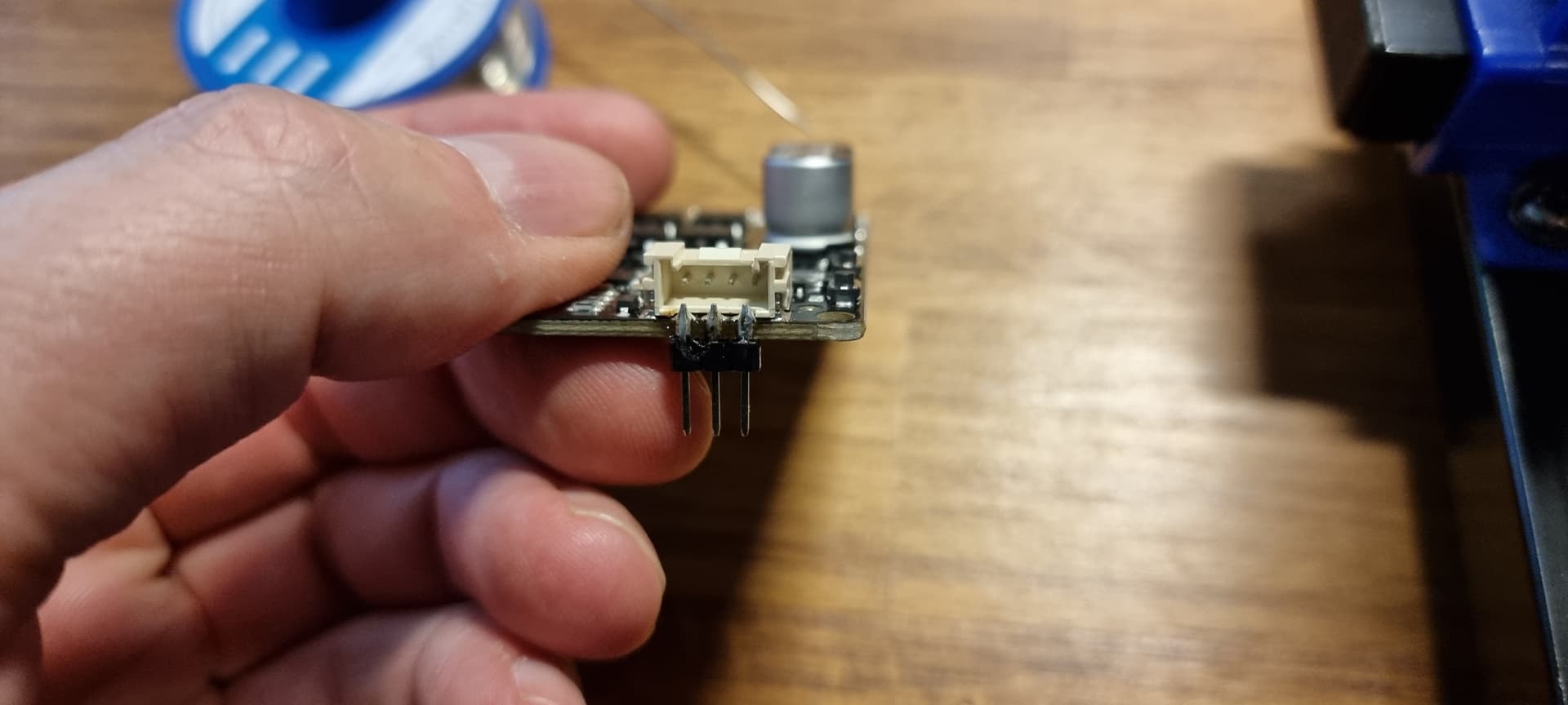
Powered back off, and you should be able to remove the Cytron easily enough and the control end will hopefully look prettier than this.

Next, I put the header pins in for the Teensy, to maintain alignment, and got soldering again. Back on the power supply, brought it up gradually again, and:

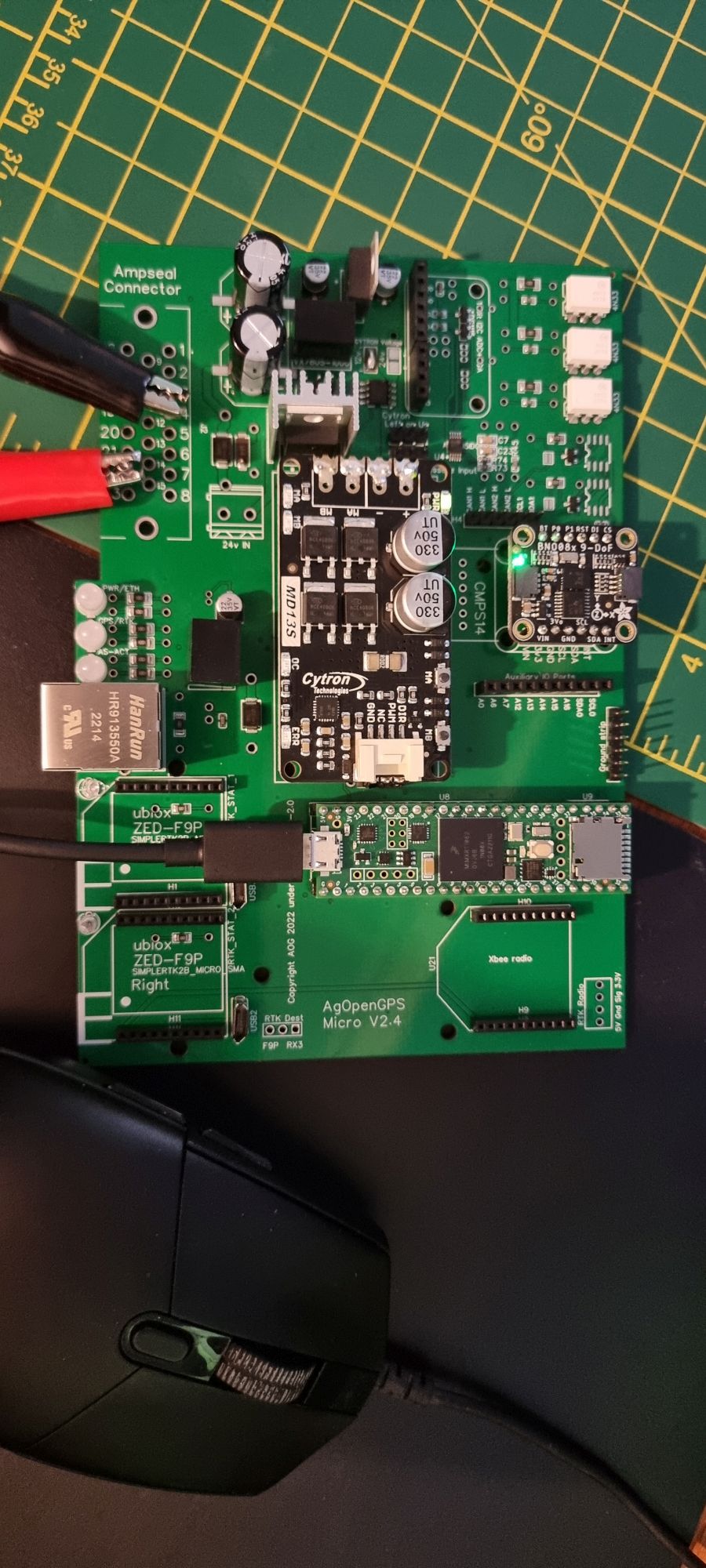
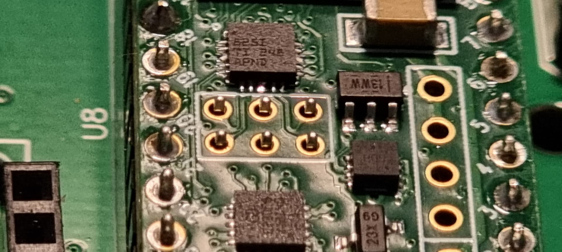
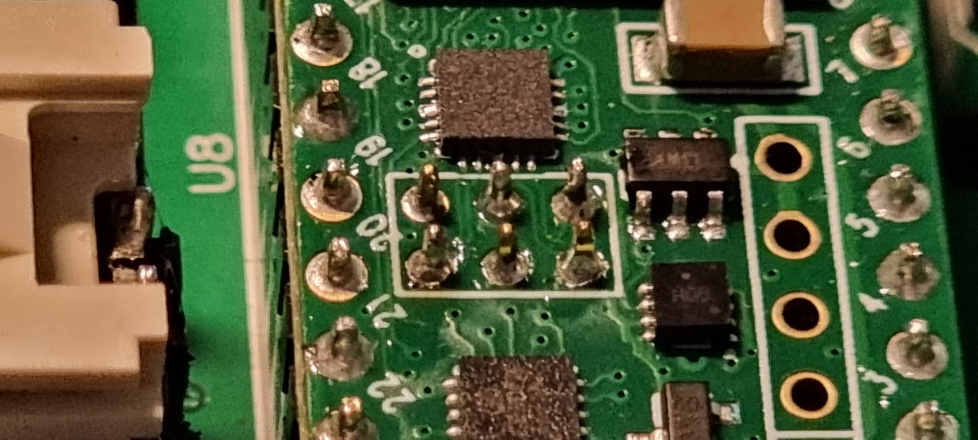
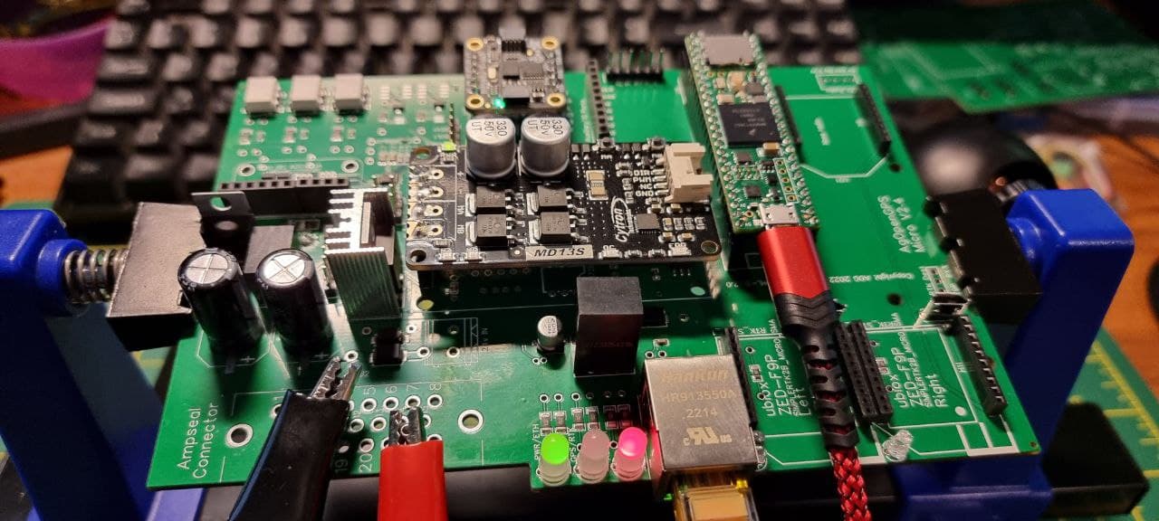
At this point, I had the default “blink” Teensy code loaded, hence the red light there. Also, I don’t have the ethernet pins for the Teensy, but as I can unplug it and refit when they arrive, I wasn’t too bothered for a test. Next, the BNO085 - placed the header pins in the board, dropped the BNO on top and soldered them to preserve alignment. Back onto the power supply, all good.

Flashed the Teensy with USB code, and back onto the power supply, and no lights on the Teensy. Hmmm… was it dead? No, it just doesn’t flash the LED with that code. Note the BNO light was on, once Teensy entered the game. Without Teensy, no BNO light.

NOTE: See warning on the top of page about not having board on 12V and Teensy on USB at the same time!

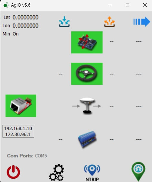
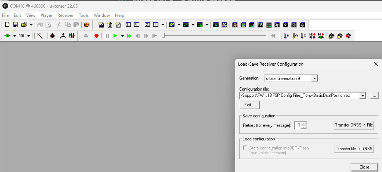
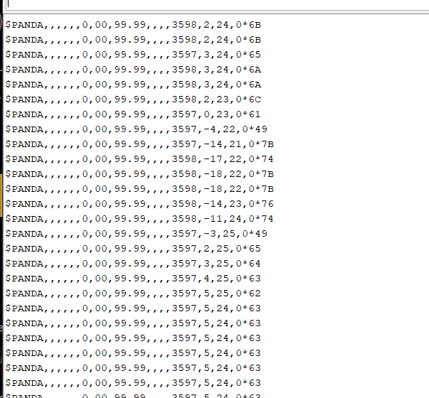
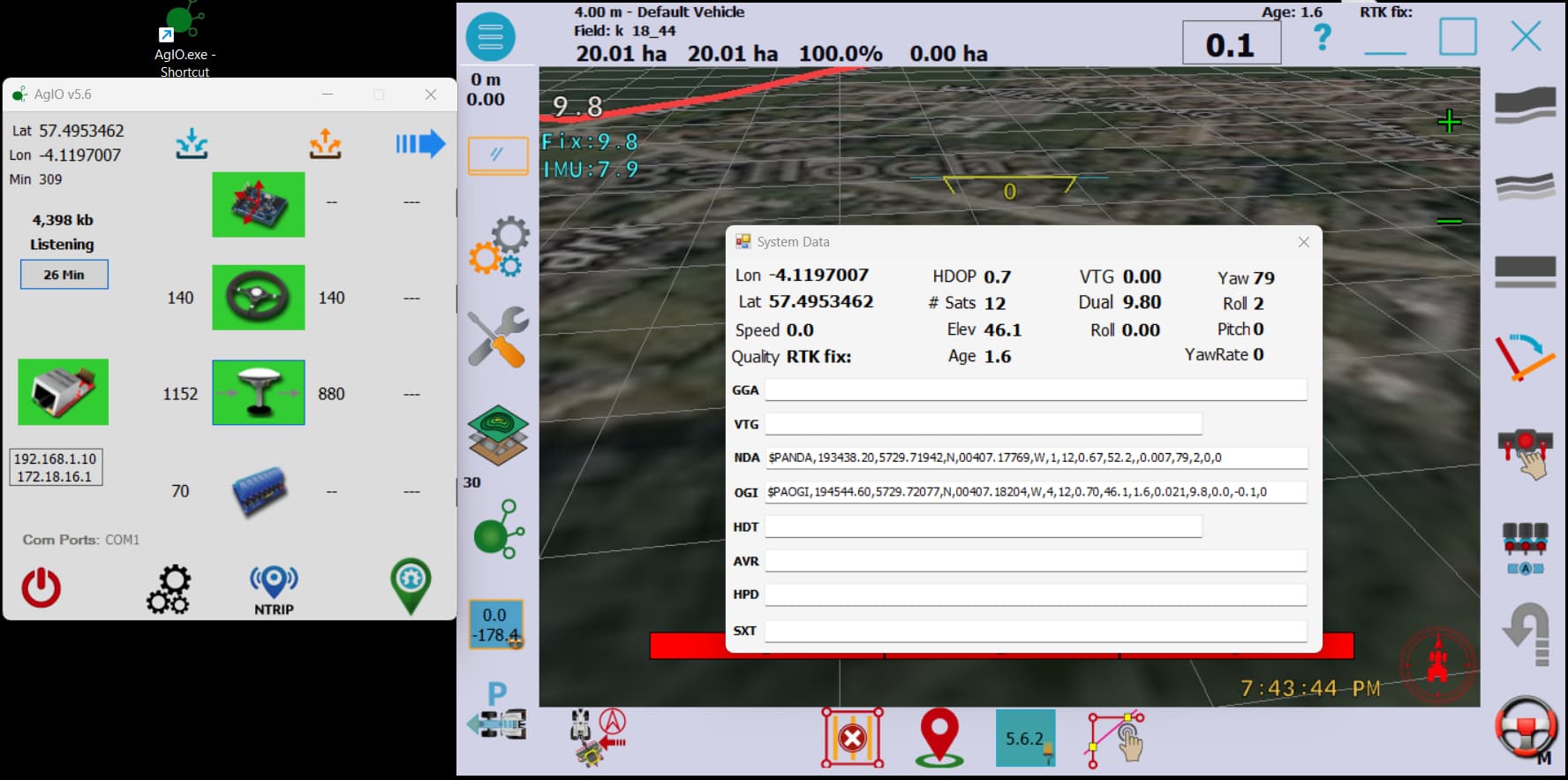
I’d already flashed it with the Panda code, so connected the USB up to the monitor on PC.

NOTE: See warning on the top of page about not having board on 12V and Teensy on USB at the same time!

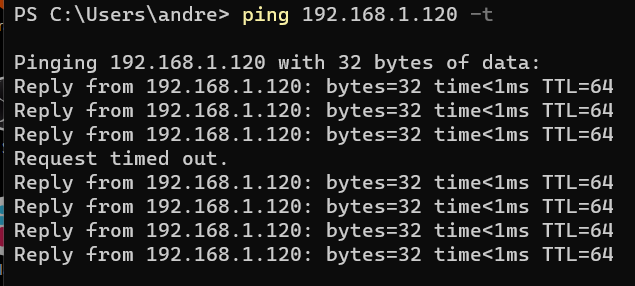
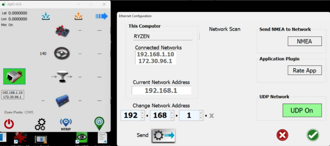
Arduino IDE 1.8 is needed to flash a Teensy remember, and the port monitor showed:

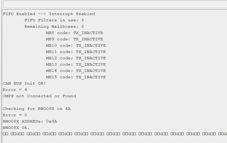
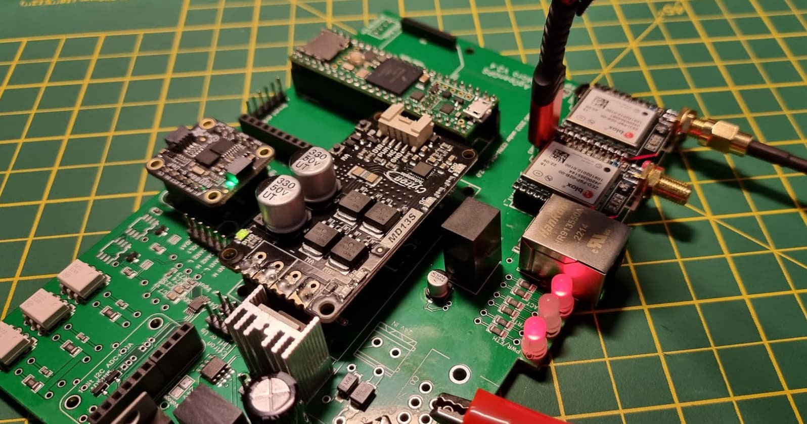
So, at this point, I’ve Cytron up and powered, and BNO talking to Teensy. I need to wait for some parts, mainly the Micro F9Ps and the pins to connect Teensy Ethernet, but at this stage, it’s looking pretty good I think.

EDIT: At this point, I should note that if you have dual antenna, you do NOT NEED THE BNO085 IMU. I didn’t know any better. Some people have pointed this out to me… so bear that in mind :slight_smile:

17 Likes

Following. Good job.:+1:

1 Like

Progress… !

Exciting email - if that’s your thing - my Ardusimple Micro F9Ps have shipped, and will be here on the 14th. Allegedly. Also, you owe DHL another £145 (bought 4, in case you’re wondering why so much) because the UK was dumb enough to leave the EU. So thanks for that…

Anyway, some ethernet headers arrived, and man they’re tiny - takes a steady hand to do these without sizzling anything you shouldn’t, but it turns out I’m getting sort-of OK at this soldering malarkey.

Before:


After:

So, at this point, I decided to hook up my USB again to the Teensy and see what it made of matters, before powering the board up. Ding-dong when I plugged it it, but no sign of life. Arduino IDE was reckoning COM5 was locked, but AGIO wasn’t open. Turns out, somehow, my Creality Slicer had locked the COM port. Closed that and all good, seeing chat on the terminal monitor again. Thought this might be a good time to explore UDP instead of USB (tho in my case, with operators using different mobile phones as hotspots and likely different subnets, that could be troublesome), and grab all the latest fixes and enhancements, and so I downloaded the latest code branch from github.

At time of writing, that’s here: https://github.com/farmerbriantee/AgOpenGPS/tree/v5NoJob

In the Support folder, there’s a Panda2/A_Teensy_v56 folder, so I guessed that was it. It was not - while I could ping the teensy, I couldn’t establish a UDP connection to/from it. I could ping the device, and that stopped when I yanked the ethernet cable out, so I knew I had the right IP:

image

How did I get that address? Well, when I uploaded the wrong code, and to make my life simple (ha), I changed the INO before uploading. The wrong file at https://github.com/farmerbriantee/AgOpenGPS/blob/v5NoJob/Support/Panda2/A_Teensy_v56/A_Teensy_v56.ino just needed a change on line 60 to be on my 192.168.1 subnet, but again, this was the wrong code. So no wonder it wasn’t working. Despite everything being wired up OK, AOG just wasn’t having it.

And the board looked like this:

Thanks to Giovanni on Telegram for pointing it out, it’s still the Basic Panda GPS/Firmware/Autosteer_gps_teensy_v5_5/ that I should have loaded. So, I did that.

And as soon as I flashed the code on…

And I got a couple lights rock up on the board too!

NOTE: See warning on the top of page about not having board on 12V and Teensy on USB at the same time!

AgOpenGPS however was not showing me any pitch/roll movement, which I was a little concerned about, as the BNO085 is right there, and it has a light on. Hmmm… Back onto the serial monitor in Arduino IDE (and because I’m on UDP, I can have the IDE and AIO connected at the same time), I could see in serial output that it was constantly going “Swapping GPS ports”. As this constituted a loop - because no GPS modules exist yet - it was blocking the code progressing to the part where it would say anything meaningful about pitch/roll etc.

In other words, don’t worry about it just yet.

And there we have it. Might start making some loom up, much tho I like my crocodile clips, as I now have the connectors. If you’re looking to order those, you want these:

Until I have confirmation I bought the right pins, coz of course they’re sold separate, I’ll keep that bit quiet just now.

But all in all, progress !

Also, someone on the PCBv2 thread asked about the ADS analog-to-digital converter, aka “the blue board” on PCBv2. If you have these components - and bear in mind, this is the Micro board - then you have it covered. If you don’t, you’ll likely still need the ADS1115 - but check with real people who know what they’re doing on that one. If you’ve some of the components I highlighted, but not all… err… I dunno.

But again, in red, if you have them, you don’t need ADS1115.

1 Like

Hold up - the Micro F9Ps arrived! Weren’t due till Tuesday… On we go! They even had the pins on already, so just a simple plug-in job !

NOTE: The warnings above about not having the board powered up on 12V and USB at the same time do not apply to flashing the F9Ps. This is safe to do.

Plugged one in to USB, but important to note that without power to the Micro, you won’t get USB recognising them to the computer. They don’t appear to take power from the computer, like the basic ones do. You can go to Firmware 1.32, and it’s included in the Support folder. Follow this guide to upgrade each one in turn:

You can get the firmware and the config files here: AgOpenGPS_Boards/Support/Ublox F9P Configurations at master · farmerbriantee/AgOpenGPS_Boards · GitHub

Anyway, there are different config files for heading and rover F9Ps.

  • (old 1.13 name) BasicDualHeading.txt / 1.32 DualAntennaHeading_RelPos / LEFT F9P!
  • (old 1.13 name) BasicDualPosition.txt / 1.32 DualAntennaPosition_GGA VTG RTCM / RIGHT F9P!

Connect each Micro F9P up over USB in turn. In u-center, go to Tools, Receiver Configuration and upload the 1.32 DualAntennaPosition_GGA VTG RTCM file to the RIGHT F9P, and 1.32 DualAntennaHeading_RelPos to the LEFT.

Pick the file and do “Transfer file → GNSS”

Then, make sure you SAVE THE MESSAGES. Otherwise, you’ll end up in Telegram asking what on earth you’ve done wrong. Facepalm icons will be used. You’ll get embarassed. View, Messages View.

That done, I returned to AOG, and…

Errr…

IDE port monitor in Arduino reporting movement on the BNO and a PANDA sentence, but of course, being indoors, no location info at the moment - but surely I was due a pitch/roll update in AOG?

So, AgOpenGPS was reporting… “AgIO?”. Two possibilities, either I had some sort of comms issue, or maybe the lack of GPS (I was inside) an issue? AoG seemed to be seeing the PANDA sentence just fine tho, and Brian helpfully advised that “AgIO?” doesn’t just mean “AgIO isn’t running”, but also “AOG isn’t getting any fix, so it doesn’t know if it is bad GPS or no agio. AgIO only sends a valid sentence when it gets a valid fix”

Unrolled the antenna cable and draped them out the window… and a few seconds later:

IMU, GPS, all working with an RTK fix!

Bonus RTK-fix green light on the board too:

And on that note… it’s time to make up the loom and head to the fields !

But first - beer!

8 Likes

cheers @andyinv !

and thanks for sharing your pcb v2.4 story. I’ll start building my first AIO board tomorrow. while waiting for the components to arrive, it was great to read about your experiences. guess what I’ve read here will save me a lot of time.

1 Like

Looking at the PCB, I noticed that the micro USB has 5v and gnd connected to the Micro (along with data lines) and I was going to suggest your micro USB might not be soldered correctly but now on closer inspection the Micro pin that USB 5v goes to is labeled as “5V to enable USB” so sounds like that doesn’t supply power after all, like you said.

1 Like

I did notice while setting up both boards that one of them had a dodgy USB connection, something for folk to watch out for. Of course you could temporarily use the other port to flash the config, then move it back, if you found yourself in such a situation.

Not much progress today as was at a ploughing competition. So I started the loom when I got home. What grief that gave me, until I realised the pins needed to be a LOT further through than I first thought. If you’re fitting AmpSeal, they need to be this far out:

Now I know they fit, you need these pins at either Farnell or ebay

770854-1 is the part number. 770680-1 is the plug that goes on the board, Farnell or ebay.

This listing is plug and contacts, might be useful. There’s a special tool to crimp them, and before the Ampseal model came out, I was building looms with these connectors (tool included). Same tool.

1 Like

for the ones struggling with the headers / pin alignment for teensy etc: I used sandpaper to make the 4-pin headers a bit shorter so that the pins will enter smoothly.

1 Like

So, not the most productive of days on the tractor. Arrived at my mates, and we fixed the antennas to the Case, and I started hacking his PCBv2 loom to fit the Ampseal/Micro. Not a huge effort, as I’d already done the power cables at home, so 5V (pin 1), WAS_H (pin2) and GND (pin4) to the WAS. Onto the hydraulic drivers, LEFT (pin 5) and RIGHT (pin 6) to them, with a common ground for the hydraulics going to pin 21 (GND).

Out to the field… ah crap, I forgot to wire up the SteerPin(8). We put a switch in line to the negative post on his tractor where we’ve plugged the power cables in, going to pin 8. Back to the shed, more ampseal fun, and once that was done…

Out to the field, noticed no RTK signal. Bit weird, was fine at home when the antennas were mostly shielded by house, but it’ll sort itself out, no worries. Opened a field, AB line… auto-steer… nothing. Hmmm… Perhaps legacy settings in my laptop or something, so started the Steer Wizard. Still nothing. WAS seemed OK tho. Damn, must have got wiring wrong, but I was really trying hard to do it right, so that would be embarassing…

Back to the shed. I had another board with me, that wasn’t stuck in the 3D printed case, so powered that up, and pressed MA/MB on the cytron. Nothing, no wheel movement! I knew from PCBv2 that they should have moved, so that wasn’t good. Multimeter out, pressed MA and tested MA on cytron to pin 4 (GND) on Ampseal - showing 12V. OK, so Cytron isn’t dead. MB also fine. But yet… when pressing MA, I wasn’t getting a voltage to pin 5, and when pressing MB, nothing on pin 6. So despite the cytron showing voltage and continuity testing showing my cable was fine, it wasn’t leaving the board???

So I was stuck… Telegram-time!

Jake kindly pointed to missing jumpers, at which point I checked the board again and noticed just above the cytron/heatsink, there’s wording to match the pin diagram - “Cytron Left or US” and “Right or Lock”. No worries, I have jumpers. It’s just that they’re 35 miles away :confused:

Dupont headers in the truck tho, so wired them up, pressed MA/MB and all good, steering again. Prised the other board out of the case, duponts onto them, all good. Back to the field!

This is what you want your board to look like and for the one obscured behind the heatsink, you want the two leftmost pins. BIG RED JUMPERS ALERT

EDIT: it was pointed out on the PCBv2 thread and in telegram that those jumpers are rated at 3 amps. In other words, I’m limited to 3A which is fine for hydraulics, but if you’re going to be driving a proper motor, essentially you now have a 3A fuse in the way. That’s not good… Refer to posts like these, of course everyone’s situation is different, you might NOT be wiring this way, but just keep it in mind:

If you’re unplugged, you should have continuity between MA and pin 5, and MB and pin 6. If you’re powered up, you’ll get 12V between MA or pin 5 to pin 4 when pressing the MA button on Cytron, and 12V from MB or pin 6 to pin 4 when pressing MB.

If you’re curious about what all that “LOCK” stuff means on the pinout, Jake replied:

Lock just sends 12v output from pwm2 when the steer is engaged. For 6/2 valve and Danfoss valves.

Back to the fields! Hmmm… still no RTK but we rolled around trying out the steering wizard for a good while. Couldn’t get the settings quite right, wondered if lack of RTK an issue.

Out with the command prompt, I could see a connection to rtk2go, so what’s the problem? Green center light on the board indicates an RTK fix, so… why isn’t AOG reporting RTK?

Chat on Telegram says “are you outputting NTRIP to port 2233” and netstat showed I wasn’t. I’d completely forgotten about the Position page in Ntrip Client Settings. So make sure yours is like this! UDP should be green, you’re very likely NOT using serial.

And just in case you didn’t know - no USB->AgIO on the new boards, UDP only.

At which point, my laptop battery ran out. (cries) So that was that. Be a good week until we get our next crack at it !

Some other things also came up today - before I left for the farm, I connected my laptop to my phone wifi, it pulled a 192.168.222.216 IP address. All fine and good, AgIO found the pre-programmed device on 192.168.1.xx that it been on my desktop earlier, so I did a “Change network address” and changed the 192.168.1 to 192.168.222. That sorted that!

image

I also plugged a LAN cable direct between laptop and Micro board. Now… I had crossover adapters with me just in case, but I knew that modern NICs will tend to sort themselves out if they detect a crossover situation, and mine did. But something still wasn’t right. UDP was green, but all devices were off:

image

More pleas on Telegram, and I was helpfully reminded that of course I’d need to set an IP manually on the ethernet NIC on laptop (if you’re a tech type, that’s because there’s no DHCP supplied on that NIC, the wifi gets a proper IP because it gets one from the phone. There’s nobody on the NIC network handing out IPs).

The worst part here is I should have spotted that - and if I was at work, I’d have clocked it instantly - but it seems to be that when I’m having a problem with AOG, instead of applying my usual skills, I immediately assume I’ve done something wrong with AOG instead. I really need to sort that, it’s embarrassing I didn’t clock that.

Anyway, Start, Run, ncpa.cpl and bring up the ethernet NIC properties. Go into IPv4 set a static IP address for whatever you like (here, I’ve picked 192.168.222.20). Subnet mask will always be 255.255.255.0. In AOG, find the UDP modules and update with “Change network address” as above.

Do NOT set DNS or Default Gateway - those are only applicable on your wifi and if you set a default gateway on your NIC when your wifi has one, you’ll cause yourself problems. No need for DNS either.

If different operators have phones that hand out different wifi IP addresses, that won’t matter - your wifi connection will work fine on a different subnet to AOG. So pick an address for AOG, set it, and forget it.

Do remember tho that if you plug your tablet into a wired connection in the house, it likely won’t work unless you happen to pick the same subnet as your home - so you may like to change it back to “obtain an address automatically” if you’re unsure, when at home/office.

Also, the tool I’m using to crimp the ampseal pins - what a nightmare it was getting some of them into the plug so now although incredibly similar to the one I was using for other plugs, I don’t think it’s quite right. Do yourself a favour, make sure it’s exactly the right tool !

> Also-also… and this is a biggie - the middle light on the board being green does NOT mean “RTK fix”. If you have an RTK fix, it should actually be off. Yeah, I know that’s a bit backwards…
EDIT: I’m seeing COMMITs in the code base that look like this is now being handled in code, as opposed to following the ardusimple layout. So soon, green will indicate RTK fix.

That’s about it for today… progress, but a lot of time wasted on things I should really have sussed on the bench first !

4 Likes

What do you do with jumpers if you.want left and right steering and wanna use a lock also??

Lock has a dedicated output.

Then why the choice??

On Danfoss you can use left for Us and right for Udc, and lock if you want a 6/2 valve for safety.

Ok thmx for explanation

Lock and Udc are actually the same signal from the mosfet.

Hello. I read your branch on assembling and setting up micro. I just don’t understand why two micro f9p and bno modules are included?

Ah, that’s an easy one - because I didn’t know any better !

Will remove the BNO and keep as a spare for pcbv2.

The translation is bad. I meant that there are two micro f9p and VNO on the printed circuit board.