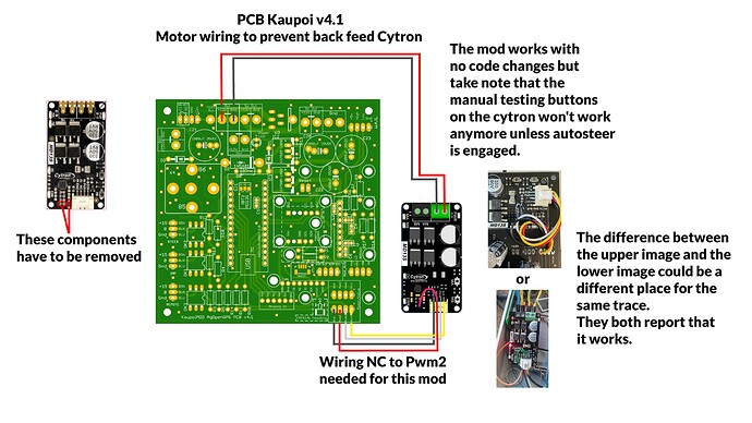
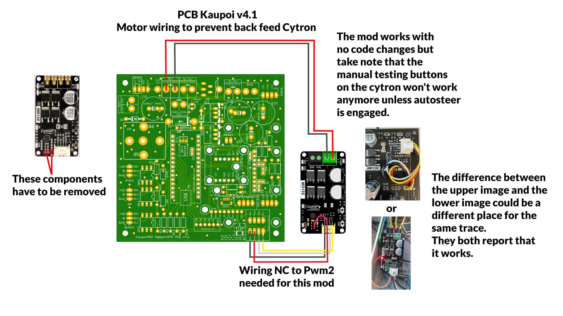
Motor wiring to prevent back feed Cytron

hello community

I’m starting my first adventure with AOG :grinning:.
Cytron md13s is not available in Poland.
How to modify cytron md20a to give free wheel? Someone has already done this?

Search the forum for free wheeling mod

Hi! Recently interested in AOG so replying to your thread back in 2021. I still can’t figure out the correct points to connect. You responded to the post (by Steigerguy) here being wrong (though PotatoFarmer indicated Steigerguy did it right) and provided a link to the correct one. I am putting the two images together below as well as a 3rd with high res image from the internet.

So the one on the left is the correct one and the one in the middle is wrong? So that is connecting NC with the encircled red will be the right connection? The two red X means what? Referring to the image on the right, so to prevent the cytron from applying a brake, soldering a piece of wire between NC and the rightmost leg of the resistor should do it? Thanks.

Both trace locations have been reported as functional

On the right picture the diode and resistor must be removed.

Both are good

Thanks all! The details in the figure is much appreciated.


This one is mine

1 Like

Nacho is your AOG functional for sometime already? I am still starting my journey and would appreciate guidance on how to proceed. I take it your board is the kaupoi v4.1. You assembled it yourself? By any chance I can get a board with all the components soldered in. I did some soldering but is terrible at it. If you or others know where I can get one, will appreciate it very much.

https://www.autosteer.cc/produkt-kategorie/agopen-set/
Here you can buy everything.

Just finished the free wheel modification on the Cytron. I bench tested afterwards and the motor is still turning but it seems to be running at a very constant speed even when I move the WAS way out of line. Is this normal or did I miss something? I did make a mistake a few days ago wiring up the 12-24v converter, I thought I dodged a bullet but I’m wondering if I may have damaged some part of the Cytron then.

If you did the mod correct your motor driver should operate the same as before. Did you connect all four wires to the Pcb?

I did connect all four wires. I think it is working as it should. I was only concerned because the last time I tested it (which was quite a while ago, I was using an older version of AOG and had a potentiometer hooked up as a WAS) the motor seemed to speed up significantly as the potentiometer was farther out of line. Then I had the mishap hooking up the 12/24 converter and had to replace that. I am now using the land rover sensor as a WAS and v5.5 and was surprised the motor didn’t move as fast. I did get another cytron in case but haven’t had time to swap them.

Hi I am using the Autosteer_UDP_v5_6 and do not have a PCB. I want to implement the Cytron free wheel mod. My understanding is that, except for removing two components on the Cytron and adding a jumper wire, I only have to connect NC (red cable) directly to digital pin 9 (PWM2) on the Nano. Is this correct? If so, why is the “new all in one bord” implementing a hole set of components for this?
Part of the “New all in one bord”:

Those components are for operating the LOCK MOSFET with the same pwm2. Note, there’s been an update/fix on the latest design and there’s always two components for each part, thru hole and surface mount.

1 Like

Ok so you either use Freewheel mod or the Lock mosfet? never both at the same time?

On the first v2.4 design, Q2/Q3 wouldn’t let the “PWM2 FreeWheel Mod” line go high enough to activate the Cytron’s with the free wheeling mod, so the latest design adds another branch off PWM2 for “PWM2 FreeWheel Mod” with it’s own protection resistor.

On v2.4 PCBs there is a fix,

Micro - cut red circled trace, add yellow circled 330 ohm resistor.

Standard

Once this fix is done, or if you have the newest v2.5 PCB, then both free wheeling mod and the mosfet LOCK output should work.

4 Likes

Bit of confusion over this - is the red wire to be connected somewhere for the mod to work?

You misread the picture. There is no wire.
Both pictures tell to cut one spot, and put 330 ohm resistor the other.
Yellow and red are opposite in the last two pictures

Sorry, I am referring to this message:

Red wire from NC on cytron is currently not used. Do I need to put it into PWM2 on my pcbV2 for the mod to work?