Hello Jerome,
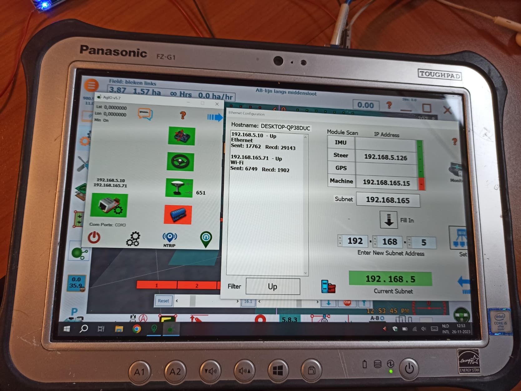
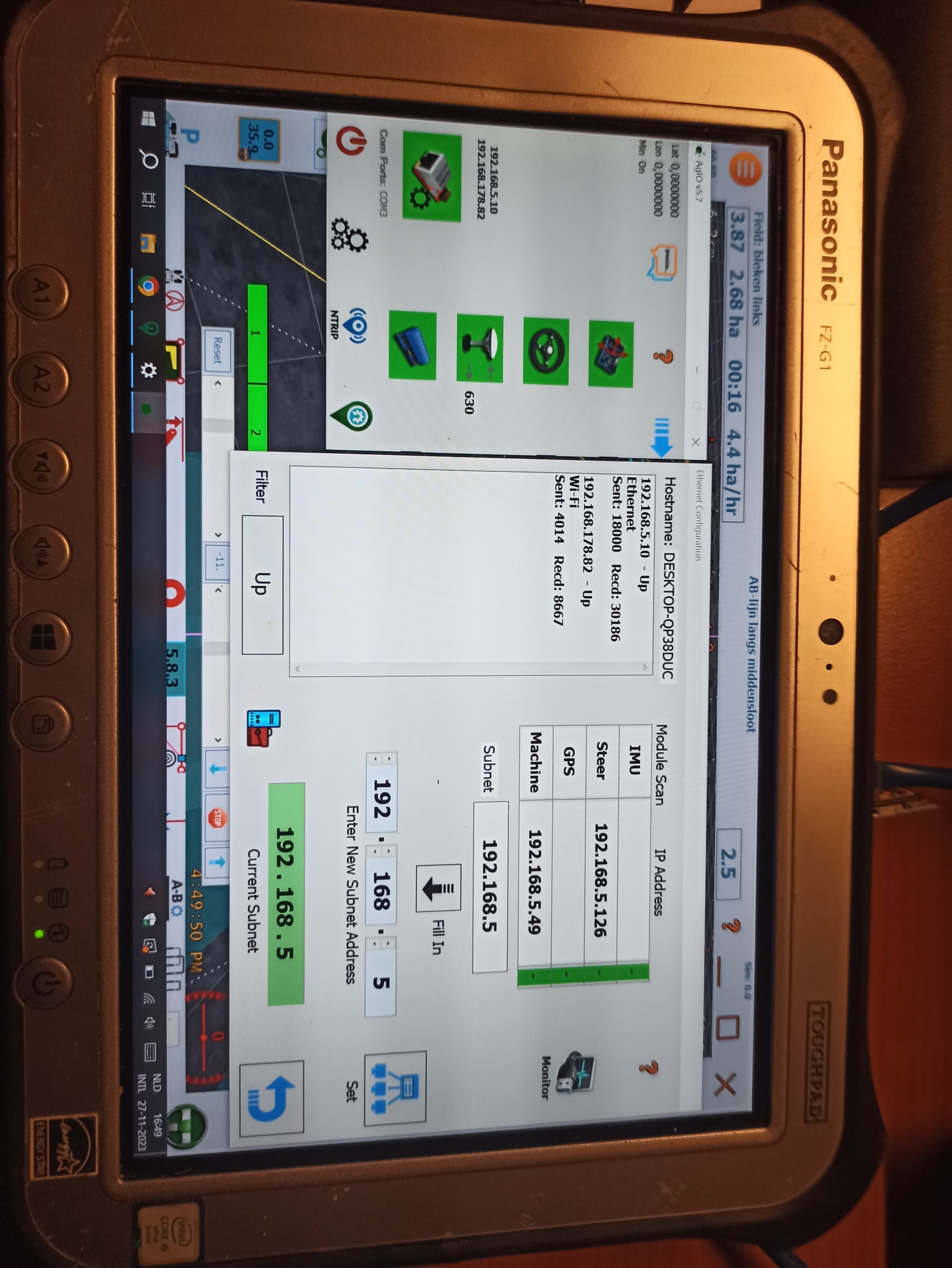
Made some progress in building section control. Only problem is that I cannot connect the ESP32 and GPS via IP adress AOG. It is one ore the other but not together. How did you do this?
Hello Jerome,
Made some progress in building section control. Only problem is that I cannot connect the ESP32 and GPS via IP adress AOG. It is one ore the other but not together. How did you do this?
can you post the sketch for arduino, I would say that you just need to change the IP in Sketch and it should work
This is the sketch.
AgOpenGPS_SectionControl_ESP32-main.zip (3,6 MB)
ESP32 connects to the tablet via WiFi and the subnet that agopengps must use is the one with the ow wifi address the address used by Teensy is from ethernets … sory I don’t know how to change it
check 5.7.2
You need a Router to manage IP’s
Correct, but a router causes delay due to package aggregation. Take another esp32 with a w5500 and make a gateway cable to wifi. This works perfect and in the end you have 1 IP area for cable
and the router is connected withe esp32 be wifi and the board is connected to the router via Ethernet, and finally the tablet is connected to the router via ethernet ??
Yes, have a video of it on telegram
I have all the materials collected to build my section control. One thing is bothering me. Sections are normally open when no current is running. Then 12 v goes to the rate computer. I am breaking my head how to do this with the optocouplers. I can do the relais, but reading switches when no current applied is possible? Should I change sketch? I looked at it and found some things I can reverse, but I am not sure wich lines all together I should change. What you think MTZ8302 ?
Use the invert relays option in the hyd lift config page.
Problem is the reading of the switches when spraying manual. No 12v applied to valve, so no 12v to optocoupler te read state of section. This is the problem I am dealing with.
Think I will manage without changing sketch. It is all about how to wire relays I see now.
Well you can change that by removing/adding an exclamation (!) Mark in the code… I would need to see the code to know where tho…
Is it possible to use this code with usb to create the conncetion with computer? I would like to skip the wi-fi part completely and run the esp trough usb. Or does it require editing the code?
So an update from this project. I am stuck… Connection to AOG is working. What I have done so far is I figgered out how the valves open and close. Give 12 volt on the togglepin switch closes the valve. Apply gnd to the according valve wire to the rate computer closes valve in the computer so rate wil be adjusted.
The Main- and Auto switch are working. But I cannot wire everything together that both are working. I put a drawing of my wiring in later. Just draw it for 1 section. Problem is that when AOG switches section off in auto-mode optocoupler 1 is activated and the section is turned off like it does in manually mode. I mean that the section-bar down in the screen turns from green to red. Do I have to split the feed of the 2 optocouplers in seperate circuits and how can I do that?
I would appriciate some tips how to go on, my knowledge of electrics are just basic so I hope an reaction can bring me further.
Unfortunately it requires code modification, I write it WiFi based because of all the people finding USB unreliable compared to UDP
Let’s work in 2 phases, first we will try to make it work in manual and auto without taking care of the rate controller status. Your relay wiring, seems a bit strange. The relay output should only go to the sprayer valve and to the second optocoupler board that we will ignore for now.
Are your valves, reverse polarity? If yes, there should be 2 wires going to section 1 valve. If spraycomputer switch section 1 is on, there is +12v on wire1 and GND on wire2. If spraycomputer switch section 1 is off there is GND on wire1 and +12v on wire2. Is that correct?
If it is correct, you should get the signal from the spraycomputer switch section 1 wire1 (12v when open) and sent to optocoupler1.
You are too late! I had it working almost, but finally on the sprayer my spraycomputer began to flash ans so on. I stopped the project, it did cost me too much time. My valves were not polarity reversed (In fact they are, but there are micro relays on the valves who tace care of it) but 12v applied closes valve. The second optocoupler for ground to ratecontroller I could not get working properly, some send gnd and some did not. solved this by using relays to send gnd to rate. Maybe problems occurd from bad soldering on the toggle switches, don’t know. Have a video of the bench test. I was very exited thought it worked.
But took very very much time, and now I have other jobs to do. Maybe next jear I will try. Here a link to my video. Sign in to your account
I understand your frustration, I also spent more hours on that project that I expected at the beginning. Hundreds of hours! Based on your video, it seems that you have an good starting point yet.
However, I would proceed step by step.