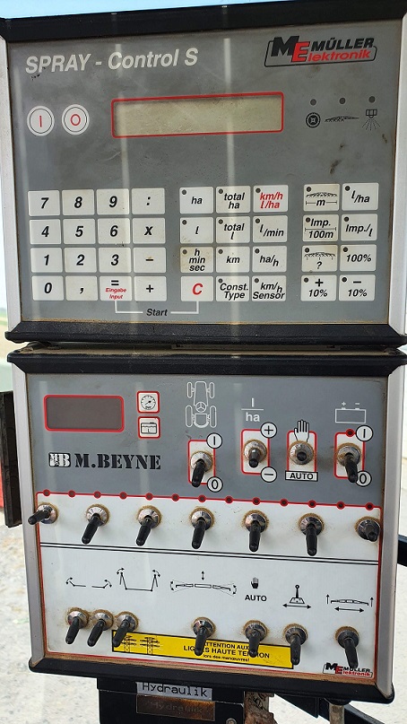
Making automatic section control with AOG for old Mueller Elektronik Spray Control - S connected with Switch-Box for controlling 4 sections:
The electronic could be set at different type of valves (with or without bypass - mine are without bypass). The control signals (12V logic) are going to the SwitchBox to turn on relays for controlling flow and also to have feedback from different switches (manual/auto, rate +/-, on/off, section switches).
This is what is looks like inside the SwitchBox:
Upper connector - connected to SprayControl
Lower connector - cable output to the sprayer
Based on the manual, I made small PCB really quick and put DPDT relays on it. I tested the PCB as a static and it works well. The problem is with through holes for relays (too small), bad pinout on voltage regulator (has to be mounted upside down), and forgot to add flyback diodes on relay coil (putted manually) - it was my first PCB, so dont judge.
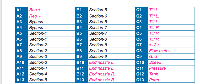
I have a pinout describtion from Mueller:
Lower connector - cable going to the sprayer:
Upper connector - connected to SprayControl
Any chance that you can re-upload the images that are not available anymore?
I would like to set up automatic section control for my mueller spraycontrol box and keep the existing box and switches and be able to use it in “manual” mode without AOG.
Has anyone integrated AOG section control with this box? How have you integrated?
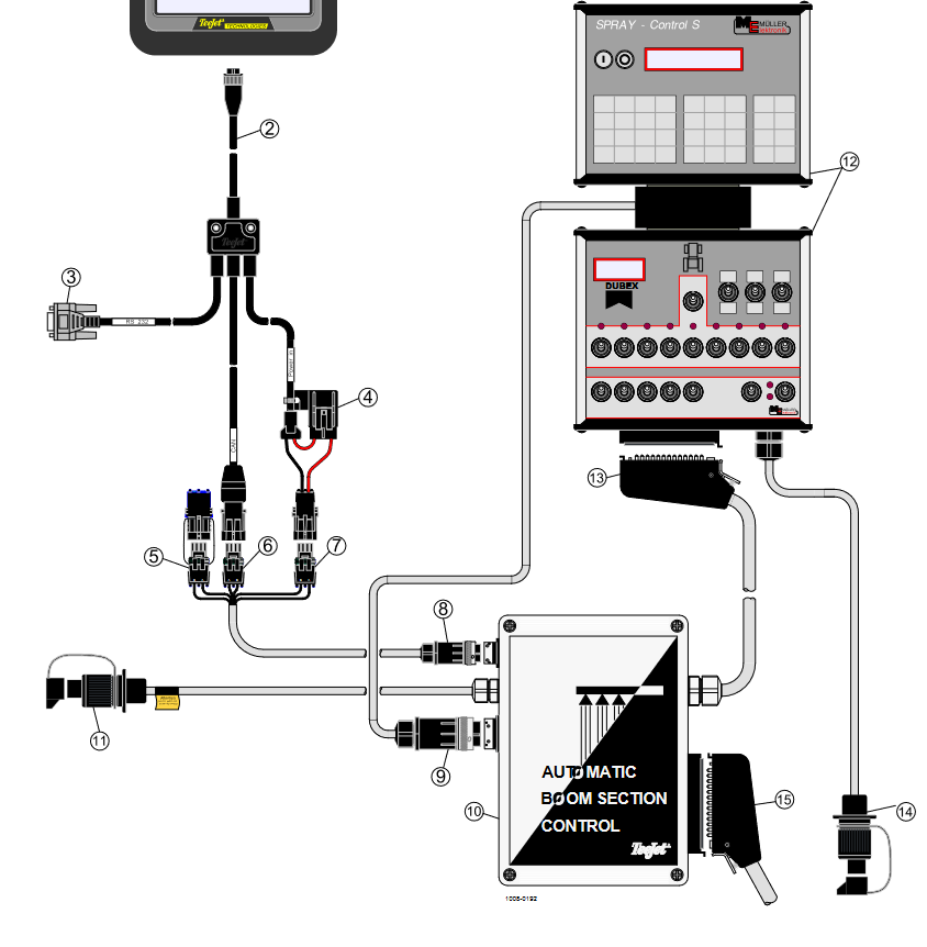
An interesting way to do it would be to use a dedicated box which connect between the 2 mueller boxes (the top one that manages rate control, width, flow, … and the bottom one with switches) and before the sprayer. I think it would do the magic without making any change on the mueller boxes. Something similar to the teejet section control box:
I’m looking for exactly the same system as you showed (the teejet boom control). I want to keep the muller box original for my fellow farmer whom I share the sprayer with . a plug and play system between the original cabinet would be a solution. did you get any further with this project?
a relay board on poe with two plugs and a udp output seems enough.
I’m still working on it. The plan is to create a box that goes between sprayer and mueller, in this box there will be the controller connected to AOG (could be USB, UDP, WiFi, …) and relays. Section signal will be read from mueller and output section signal will be coming from a relay board. Controller will read section status from mueller box and it will manage the relay according to AOG (Manual/Auto). So no new switch needed except for switching Auto/Manual.
Note also that from this box there will be a cable going to another small box which fits between the 2 mueller box. The reason is that section signal must be sent to the top mueller box (spray control) so that it can calculate the rate. It needs to know the section status from the relay (when spraying in Auto mode).
So with this setup, you can just unplug the 2 boxes and switch back to original mueller system!
I ordered a lot of components (optocoupler board, ESP32, relay board, connectors harting to connect between mueller boxes, din 41622 connectors to connect between mueller and sprayer, wires, …) and last ones should be delivered…today ! So I expect moving forward on this in the coming weeks. Hopefully I can spray using AOG this spring
So, here is the status right now.
The section signal is read using a PC817 optocoupler board and ESP32 is running my MTZ forked code which connect to my mobile hotspot and does UDP with AOG v.5.7.2
I’m using a 16relay board because I need 2 relay for each section (reverse polarity) and there are 7 sections. I will add another additional PC817 board after the relay in order to send GND signal to the rate computer when sections are open.
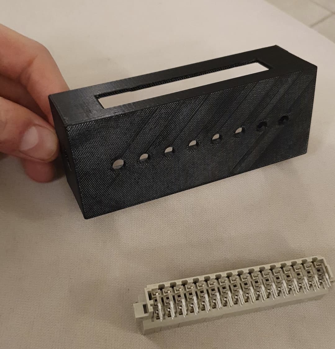
I have also 3D printed a box that will fits between the müller boxes and which contains leds for real section status (relay output) and the man/auto switch. This boxes will just forward signal between müller boxes except section signals that will be coming from relays status.
After a few months of thinking, designing, analyzing Müller boxes, reading Discourse topics, Github and Telegram chats, section control for Müller Spray Control terminal is finally working
The section control unit connects with the existing Müller boxes to do AOG section control and no modification has been done to the original setup. So the unit can be unplugged from Müller boxes and you’re back to the original system.
In the unit, there is an ESP32 controller that connects to AOG using WiFi UDP and is activating the relays based on switches status and AOG instructions. In manual mode, AOG is drawing the working area. In auto mode, AOG controls the relays. An optocoupler board is used to read switches status from Müller box (motor valve with reverse polarity) and another optocoupler board is used to send section state to the Spray Control S rate computer.
A 3D printed box that fits between Müller Spray Control box and the switches box has been designed, it connects to the Spray Control S box and send the section signal from real status(relay board+optocoupler). In order to centralize the switches, the man/auto switch has been put on this 3D printed box. 7 leds have also been added to show the section state based on the relays as the original led only shows the switches state.
Here is the demo:
The ESP32 code is based on MTZ code for which all the rate control and web interface related stuff have been removed. It has also been updated to connect to a WiFi network and communicate to AOG v5.7.2 UDP.
Do you think this would work with Amaspray + also? It is also mueller made and after reading about your project it seems that it functions pretty much the same as that older version. Basically it is the same but the switches and rate control are in the same box if I have understood correctly. If you have more pictures of your assembly could you post them here? Would be much appreciated.
Anyway your system looks very good!
For my skills it’s too complicated to make it wireless and respond to switches on control box etc . Im gonna go simple way with polarity inverting via AOG. All all the time on and AoG controling sections. Maybe on Amazone possible to go this way? What type of section control valves is there on your sprayers?
Thanks, have you looked at the wiki in my github?
It contains a lot of details on the wiring and the components that have been used. This could fit any kind of sprayer controller you just need to wire the section signal and the output signal from the relay to the valve and rate computer. Note that you need to understand what kind of signal does your rate computer need.
Let me know if you are interested on more details or picture on some parts but the box is full of wires and components so that’s not as clear as the wiring diagram on github.
Don’t forget to send the relay status (real section state) to the rate computer otherwise the calculated area will be different than what is really sprayed and your spraying rate will be erroneous.
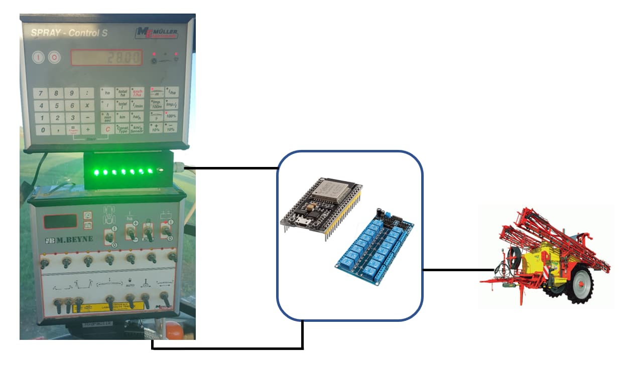
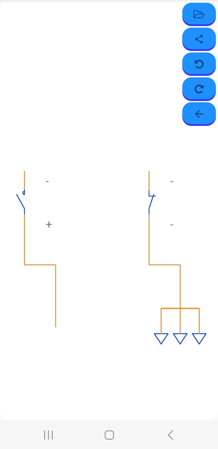
hello I made a section cut on a sprayer with a polarity inversion too but in fact by analyzing the original system the polarity inversion is done alone so I just bypassed the original switches. I send you a diagram
Origine :
Hi Jerome,
I understand that computer will be showing wrong calculations of water rate. The main problem that I’m not farming, trying to make life easier for my father and can access equipment only once in a while on weekends. And between that only can prototype at home and hope can install quickly in short time.
By the way anybody knows if those old Mullers can actualy ajust flow rate automatically or only showing actual flow of chemicals? Bought used equipement with broken pressure release valve. Must change it to mechanical. Electrical would consider if computer actually could control it.
Yes they are automatically adjusting the rate, that’s why the computer need to know the boom width which is spraying to adjust the rate in real time. The rate keeps constant whatever the speed and number of open section. This is controlled by a reverse polarity valve that adjust the flow going to the boom.