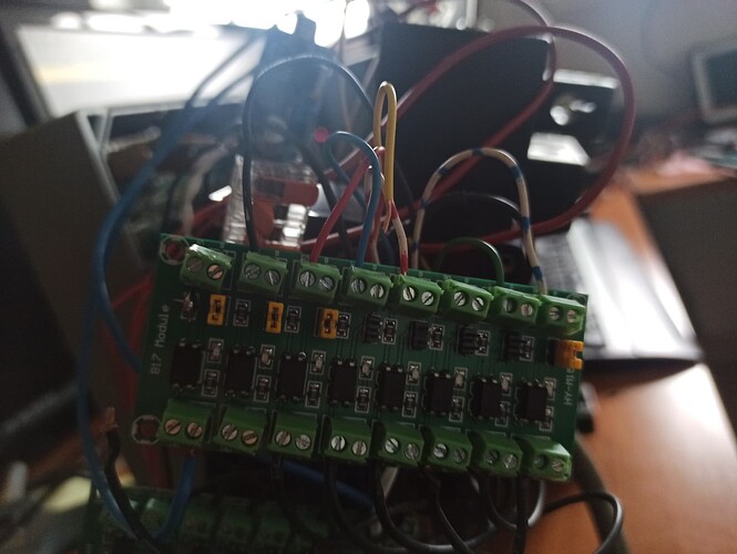
I have SC working with esp32. I have 1 optocoupler to read the sectionswitches from sprayer to tablet. This works good now. Esp32 controls relayboard for switching sections. This works too. This relayboard is connected to optocoupler 2. This optcoupler should give gnd signal to rate computer so rate computer knows which scections are open or closed. Input of the 2e opto works (leds light up when switched) but no gnd connection is made for rate computer. When I put section wire directly to gnd rate computer switches. So how to get a gnd signal out of the opto board?
Measure how many mA when section wire is put direct to Gnd?
In one of my links this is stated: Warning: Optocouplers have a low output current. For example, the maximum output current for PC817 is 50 mA. You cannot connect high-current components (such as motors, etc.) to the optocoupler output directly. You must use a transistor to supply current in such cases.
So if you measure below 50 mA then short the resistor at the output ( the 3 K ohm one) Because that resistor prevents the voltage on wire from rate computer to go low enough.
EDIT Edit: First you Must ensure there is GND connection from opto board to rate computer! I can´t see your GND wire on the picture above
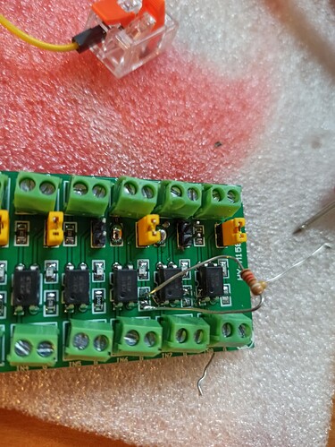
Gnd is wired correct, I have gnd where it should be. I started measuring resistance over the output terminals of the optocoupler. I discovered 2 of 8 on the board are broken, 0 resistance when not powered. The other when powered 3700 ohm resistance, I bridged one of the resistors and then 700 ohm over terminal. This is to much for rate controller to overcome. Can I change something else to let the optocoupler work? I can use relais I suppose, but then my box is to small ![]()
I can not measure mA, my multimeter is not good enough for that.
Was that when the optocoupler is activated.
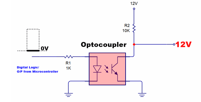
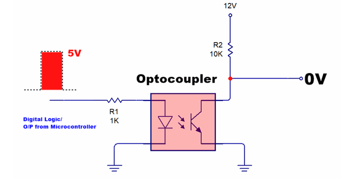
How it works:
Input low → Output open = VCC
Input high → Output forced to GND
You need the resistor in the output circuit!
Check out, if there is voltage when input is not triggered
if you measure gnd if not triggered
yes, activated.
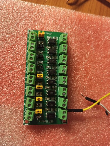
This is my board. The one the wire is attached to is the resistor bridged. So when power on the input side(yellow cable) and led shines not enough gnd to pull rate controller down.
And when you connect rate controller wire to the gnd beside U1 then rate controller is pulled down correctly?
yes, direct on gnd it works
Switching to gnd the led of the toggle switches for sections start burning bright. With optocoupler they shine just a bit and no switching rate computer.
I see 2 options!
1: your optocoupler work with a range from 3.6 to 30 V input, and the resistor is 3 K ohm at input. Then add another 3 K ohm resistor to double the input current, and by that reduce the resistance at the output side. (The output optotransistor get more activated)
2: Or use the 16 relays board you already have, at each input you add a resistor of about 2K ohm to be able to use 12v in. Now the corresponding relay can be used to switch to GND
Will try option 1. If not succesful I will mount wextra relais and buy a bigger box for the system.
So I did remove resistor 3000 ohm and replaced it for 1000 ohm. Now this one works! It pulles my rate controller to not spraying. Is there an optocoupler bord with these smaller resistors or should I modify them one by one? go search for a board.
I did not find any much diferent with PC-817 Optocoupler. Maybe you could scrape away some green lack and dril a hole for one end of your resistor to make it more stable and easy to mount (hopefully there are no cupper at the other side of pcb.) And without touching the GND area that is very close.
But maybe this one it has by looking at the colour of resistor 2,2 K ohm (brown black red). Atleast it is easy to change R1. Have seen it with 2 opto modules.
I just put a bulb of solder on that perticular resistor that it is out of the circuit. Than I took a 1k resistor and put that in the connector and soldered my wire to it. Think it works but ran out of resistors. Ordered them so hopefully iI can finish SC Monday.
Thanks for your help, learned a lot about electronics.
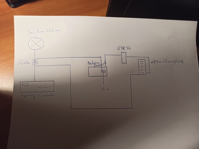
So I finally got it working. the BIG problem I was facing and have been struggeling with was that I did not know how to split signal from 12v to sectionvalve. I sat down in the barn some afternoon and made a drawing like this.
The problem was that my valve closes when 12v applied, then the optocoupler gets signal and esp32 wants to open valve. My breakthrough wa to place a diode between 12v wire from relais and 12v to optocoupler like you can see. Still have a feeling this might be solved in the software some how.
Next problem was to get my spraycomputer shut sections off for rate control. The optocoupler with the bridged 4k resistor still could not pull valve to ground and shut off. solved this by replacing incoming resistor 3k for 1k resistor.
Connecting to AOG I use WiFi hotspot cellphone, connect tablet and esp32 and bridge wifi and lan in tablet. This works for now, maybe hotspot from esp32 might be easier. A short video can be found here. https://www.youtube.com/watch?v=708QgS6_8Ms
Thanks to you all, was quite a journey to discover how everything works.
Bridging ethernet and wifi made machine module working alongside steer module. But now I have only single gps, cannot get a fix. I think somewhere too much delay or so. Gonna switch to router, then everything works and no different ip adresses after new boot boards.
I just got a new sprayer that has Amazone version of the mueller control box, Amatron II A. It looks very similar to this Mueller one so I think it could work the same.
I am looking to build this section control this winter time. I have couple questions tho.
How do you wire led lights?
Does Relay section x on the first ESP32 board mean that you just pull wire from the corresponding 12v from the relay board?
Is it possible to wire this to use ethernet cable instead of wifi?
