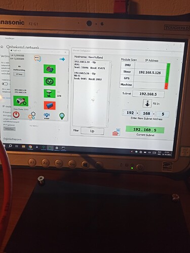
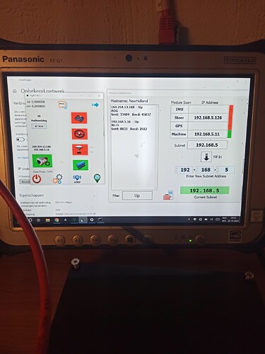
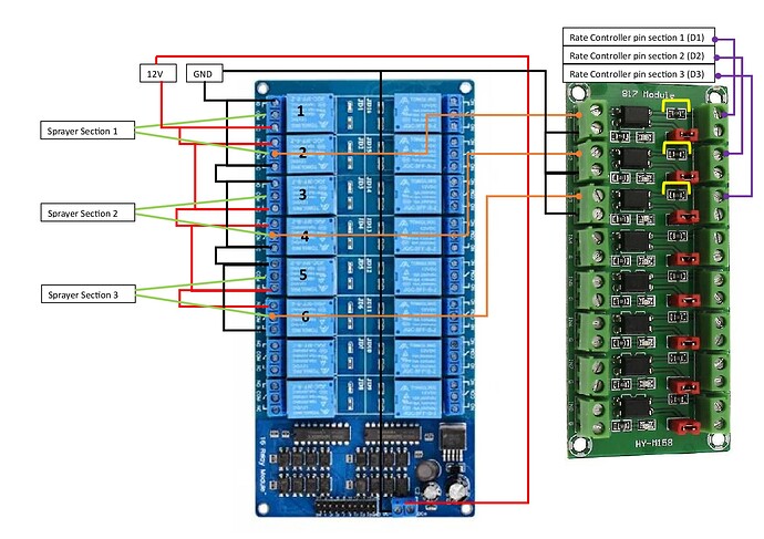
Picked up the project again, think I will succeed. Thanks for your help above, I messed relays and rate up. Have to see them as seperated projects I understand now. Only thing I am struggeling with is the ESP32 connection. I use a router now for the ESP wifi signals. Sometimes connection looks lost and Agio pops up in the screen. RC keeps working, but constant Agio popping up is bad. How did you connect ESP to AOG?
Can it be done with wifi directly to phone or tablet?
Use a w5500 ethernet adapter for ESP?
Depending on your whole setup… I don’t use ethernet for autosteer/teensy. So I’m doing a hotspot on my phone and connect the computer and ESP to that WiFi hotspot. The computer and ESP are then on the same network and able to communicate. That’s it.
Tried that today. Was not working, how to set IP adresses tablet and ESP?
Use the esp32 hotspot and an external antenna. Works good. No dropped connections.
I connected ESP to my phone hotspot. But now I have problem with Agio. Subnets are different so I can steer or I can connect to machine, but not both at same time. Is there a solution for this?
You mean an extra ESP32 for hotspot?
I guess your autosteer module connects via ethernet, right? The problem is that, as far as I know, AOG doesn’t support 2 modules (autosteer and machine) to be in different subnet ![]()
So that become an IT problem since you need to figure out how to connect the ESP32, autosteer and computer in the same network. I’m not using autosteer so I’m not facing that issue. You could switch one of the module to USB or setup a home router that connects all together.
Use the same esp32 and create a hotspot. Connect the tablet to the esp32 hotspot. The tablet can still connect over ethernet to the steering module.
I am trying to create an hotspot on the esp32. But I do not know where to begin. I can put simple setup in sketch but then lots of errors, not compiling. Should I change the initwifi (zAOG_sc_comm) or where to begin? I am a noob in programming…
If you are using section control from Matthias (MTZ8302) it’s pretty easy:
after powerup, software will try to find Wifi clients, after timeout (approx. 60 sec) an ESP hotspot will created automatically!
Looked at Matthias sketch. It is not the one I use. Now I was trying to set up hotspot with second esp32. But there are some conflicts regarding IP adresses I think. When tablet is set to fixed IP only steer modules connect, set to DHCP only machine turns green. What am I doing wrong, set both subnets to 192.168.5.?
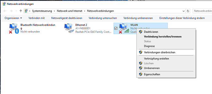
If you have autosteer connected to LAN Port and sectioncontrol connected via WLAN Port then you have bridge both ports on your computer.
If you would use Matthias code, you can go with your router because it does not support that new watchdog feature between SC and AGIO so AGIO does’nt pop up. I’m running this section control for years without any problems. (Mikrotik mAP router)
-
how far away is your ESP32 located, how is the signal strengh
-
you can use a W5500 module an connect the esp32 hardwired (supported by Matthias code)
I bridged LAN and WiFi and now it works. Will try Matthias code too, see how that works. Thanks
I am working on it again. I follow the steps in this writing, connected the line to valve 1 to optocoupler 1. I can read the section state, manually as automatic.
After this I try to connect the relais for section one to the line going to valve 1. This is the same line where the optocoupler is connected to.
Now my problems start, because the switch on the spraycomputer and the relais can feed the same line to valve 1. In some combinations i get weird behaviour of the relais, they start jittering or will not open. Should I seperate feeding the valve or something and how to do? Or disconnect switches computer? You have a hint for me?
So white is 12 volt power tractor. Brown is wire from valve section 1. Opto connected to brown for reading status section 1. Is this wiring good? Problems occur when computer closes valve(power to brown), valve 1 close. The valve will not disengage when computer should continue spraying (relais doesnt klick) until disconnect wite to opto.
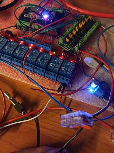
Do you have separate 5V supply to the relay pcb. If not enough 5V they will jitter!
I have a 8 relay pcb with the posibility to change/ shift between internal and external 5 V , with a jumper .Like this post: Powering 8 Channel Relay Module Problem - #7 by steigede - General Electronics - Arduino Forum
Got it working now, later I will report my solution. Only problem is the rate controller. I have to switch rate to ground but optocoupler is not doing the thing like as described in the github. When I manually touch the wire to ground the rate computer switches off. Any thoughts?
We do not know which relay module you have. Is it a relay high or a relay low type? (turn on either by 5 V to signal input or by 0 V /GND to signal input)
The link below show a relay type that can do both, you can set some of relays high, and the rest as low.
I mean this part. I have signal from relay, but want gnd out for switching rate computer. I do not understand opto really, did as in picture but it is not working for now. I bridged 1 resistor as shown in the picture, can I have damaged the optoboard?
EDIT: The following statement is wrong because I did not check the schematich for optocoupler:
I see problem in wiring. The orange colored lines from opto to relay board should probably trigger the relay board? in that case you should wire the orange ones to the relay input that I suppose is at the lower part of relay board. Next problem : Is the relay board active LOW ?
EDIT: My bad It seems the optocoupler board is supposed to read the state of 12V at the IN side.
https://support.envistiamall.com/kb/pc817-optocoupler-isolation-board-voltage-converter-modules/
This then lead to next question: What should trigger your Relay module?
