Hello everyone, I am on my journey to autosteer, but I am currently trying some breadboard designs. I cannot get the WAS reading from the potentiometer, even though it’s all wired correctly. When I measure with a multimeter I can see the voltage change. I don’t have the ADS1115 yet so I am connecting it to pin A0. Is it possible that the newer arduino script doesn’t support direct wiring of was without ads1115? If so, does anyone have the old arduino files so I can try out this breadboard design first?
In AOG I get -269 degree steering angle and it doesn’t change at all.
Really would appreciate if anyone can help me out.
Welcome to the forum ![]()
A0 (on arduino) is today used for pressure and/or current, cut off of autosteer.
You should really get the ADS 1115 ![]()
On Github where you get V5 you can click on releases and go back in time and find V4.
Program version and INO version MUST fit.
INO is normally in support ZIP
Edit: Sorry for not being able to point out where the schematic showing the new A0 is to find. I could not see that info in Ver 545 support folder!
Thanks for the reply. I am going to use an ads but was out of stock at most places so I ordered it via aliexpress and it will probably be 2 months until it arrives. I was hoping that someone might have the whole folder that went with Autosteerpcbv2.ino since that’s what Brian was using in the YouTube video and it gives the option to not use the ADS1115. Or if anyone has a modification to the arduino file so I can connect the WAS directly to the board. But it’s really confusing putting everything together with the old schematics in the wiki.
I would think changing the .ino slightly to accept A0 for instance as a WAS reading would be reasonably simple. A bit of multiplication would be required as the ADS is higher resolution.
Would get you going until you could get an ADS.
So, for instance, replacing the ADS differential mode code with something like
steeringPosition = analogRead(ANALOG_SENSOR_PIN);
then multiplying it up to fit the 0 to 13610 range required.
ANALOG_SENSOR_PIN because A0 is already defined as such in the code.
Commenting out the ADS related setup might be necessary.
Thanks a lot, that is helpful, I’m sorry but I have got no idea how to code anything. And what do you mean by multiplying? Is it something I should put in the code?
Really appreciate when you guys help.
Ok, someone else please check this. A quick hack to put the WAS onto A0. Multiplied A0 by 13 to get roughly the same output range as ADS. Obviously isn’t compatible with pressure sensor usage.
It compiles ok but I’ve not tested it! I’ve assumed you are using the USB version.
So I tried it out but still can’t get anything in AOG.
My current setup is an arduino on a breadboard, pot taking 5v from the breadboard and middle leg connected to A0.
Is there a chance the arduino isn’t receiving the code? It says upload completed successfully.
Does the resistance of the pot have any effect? It’s a 50 kohm.
The other leg of the pot is connected to ground I assume?
To be clear, middle pin to A0, one end to 5v, the other end to GND.
10K seems to be the go to size for this type of thing but 50K should work.
1 Like
Yes, connected as you said, restarted the arduino a couple times after getting frozen was values, somehow I started getting WAS reading. Thanks a lot, going to try out controlling the cytron next.
Cheers really appreciate it.
1 Like
Have you sent the Arduino config command from in AoG settings?
1 Like
I am not sure what you mean, can you elaborate? I only setup the arduino via the arduino program, didn’t see anything to configure in aog other than ADS, and the other sensors.
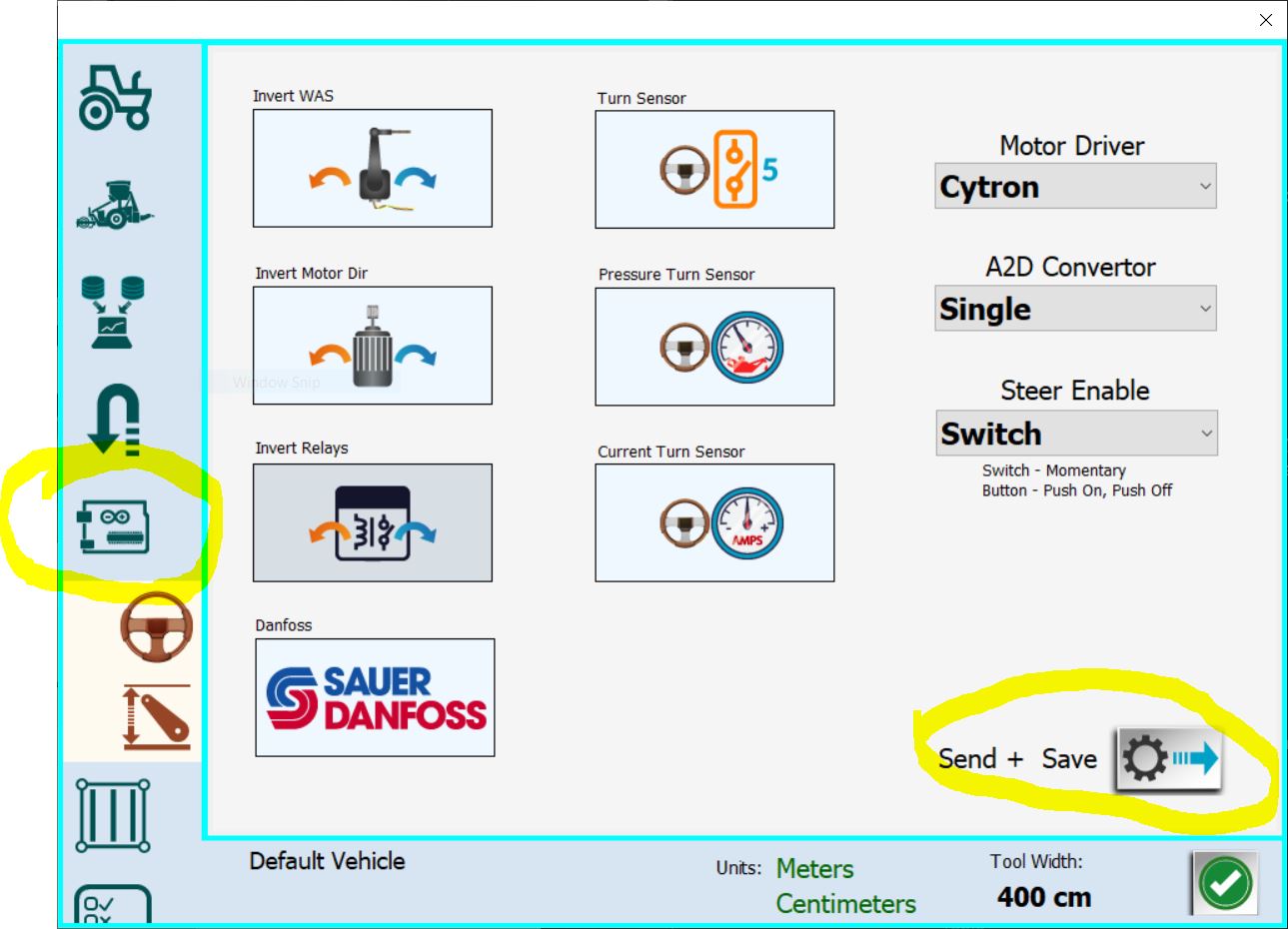
Module configuration, after entering the settings in AGO, the icon in the shape of an arduino uno, you have to send the settings at least once. Also move the WAS 0 slider to the right and left, only then will it start grinding the program.
1 Like
This is in the steering tuning window where you set WAS counts per degrees.
When testing, make sure you have a working GPS connected or at least simulated GPS. Aog does not do much when there is no position…
Does a2d single mean no a2d converter? I did try these settings first but without any luck. When I tried Alan’s modification to the arduino sketch I got the readings finally.
Also I did manage to get the motor to respond with simulation mode on, now I have to start thinking of a way to mount the WAS.
Cheers
@Alan.Webb 's code above is modified for your application, so if you pick “a2d single” it read the A0 pin no ADS.
In the regular ino code:
a2d single mean the ADS read only the voltage of the WAS signal wire.
a2d diff mean the ADS read the difference of voltage between WAS signal and ground, to use if you pick the signal from OEM WAS.
1 Like
Yes, I just deleted the ADS read code completely and forced steeringPosition to be read from A0 whatever the A2D setting. I could have left one ADS read option in but I wanted to be 100% you were getting steeringPosition from A0.
I will probably make a thread about a breadboard version and include your code and what pins need to be connected in a picture since when you look on google all you get is the old design which won’t work if you want to try things out on a bench first. Will make sure to credit you of course. Just want to help newbies having trouble trying everything out for the first time.