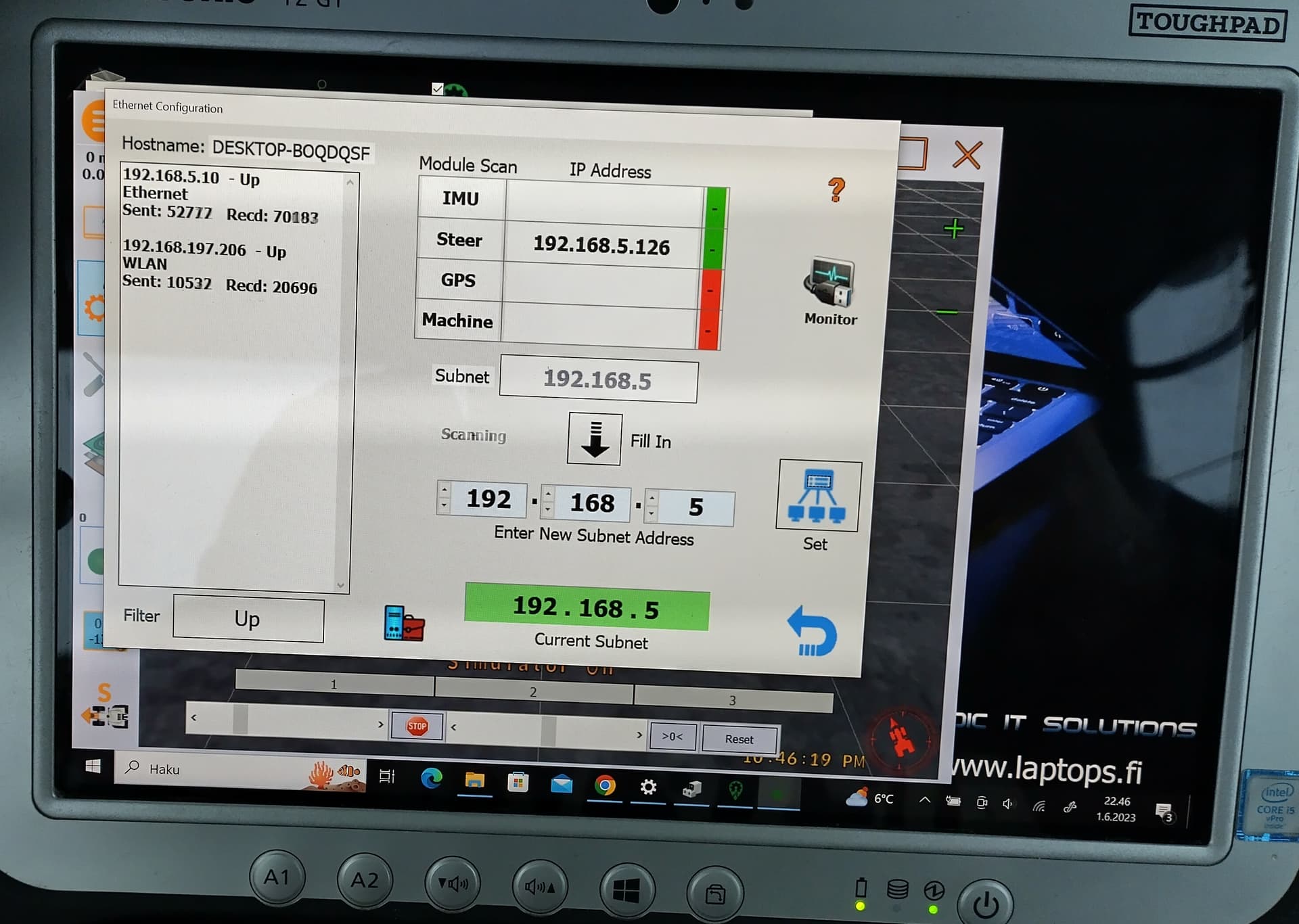
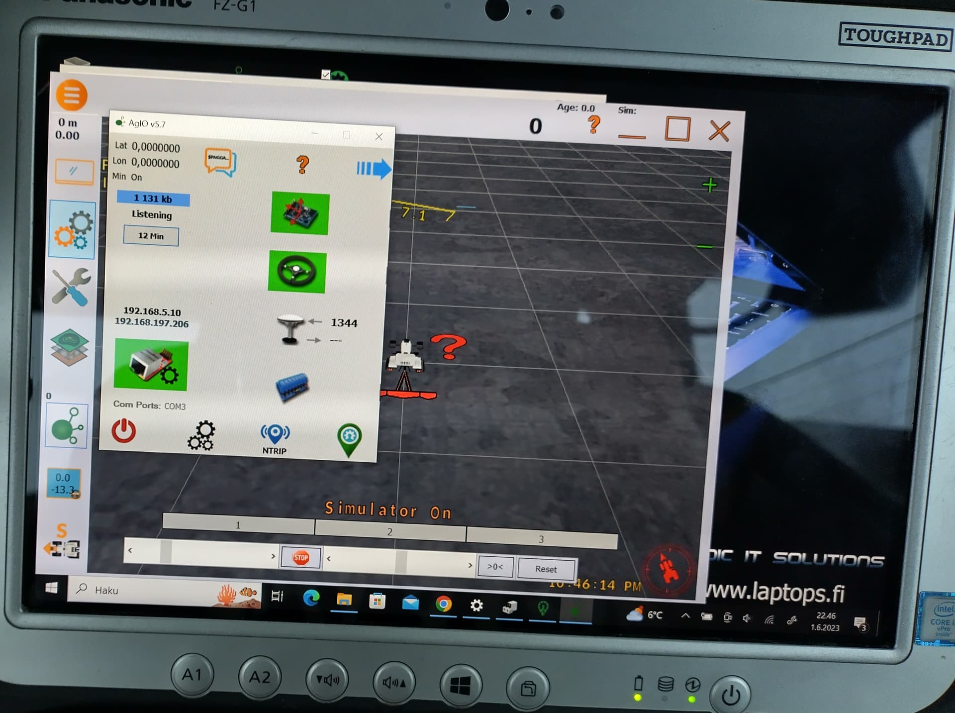
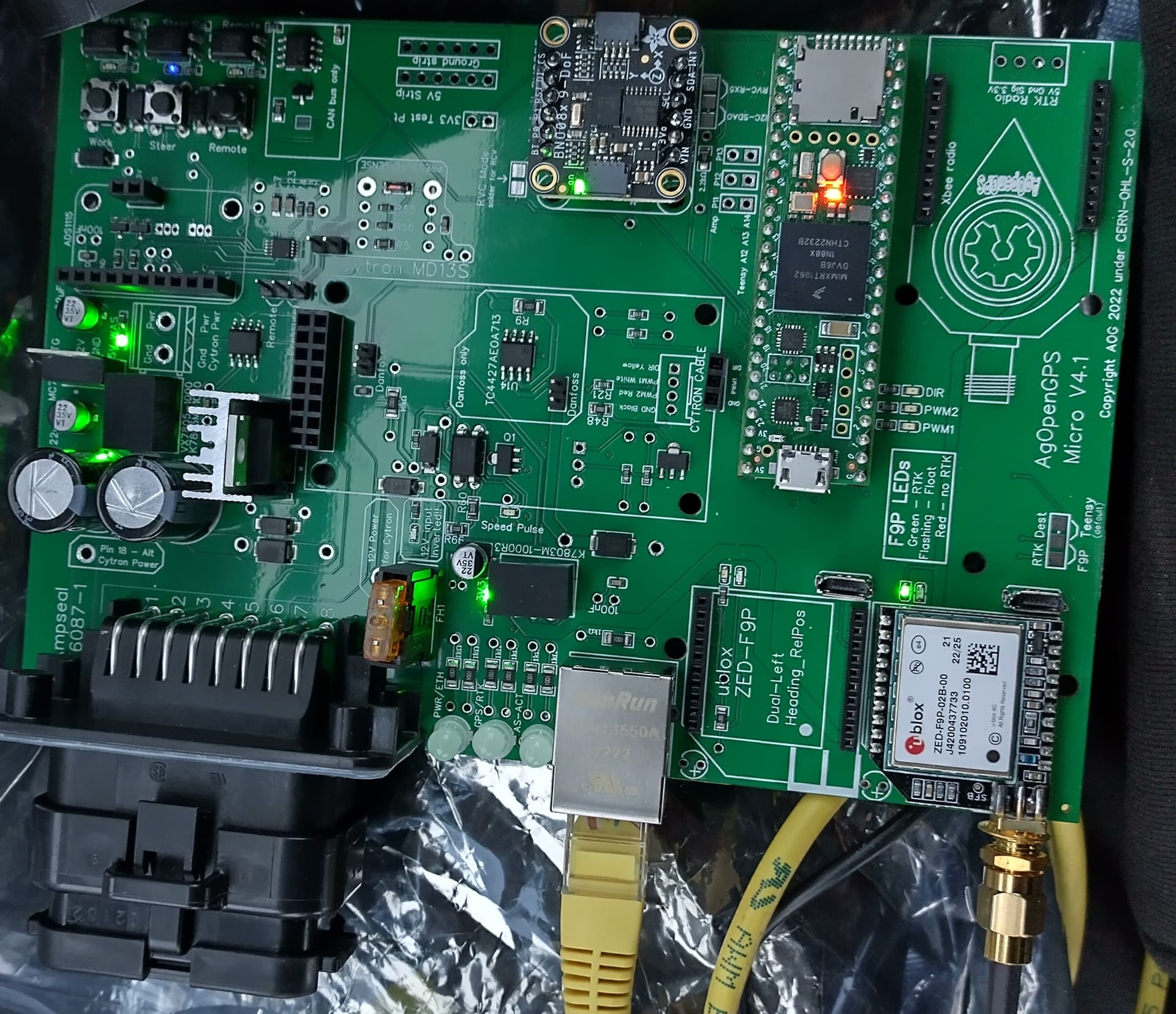
There is no light on pcb’s 3 leds. F9P led goes red very easily when touching antennas wire( I think that there is something wrong there). I Have 1.32 files on my micro. I had WAS(canbus) and IMU working earlier and these are still working. I Have 5.7.2 aog
I think I had it right. I uploaded it again without //. Now light next to F9P does not go green at all. It is only red and the light is not allways that bright. Problem might be in antenna cable, F9P micro on pcd soldering or somewhere else🙄. Can it be powering pcb? As you can see, the 3 leds are very dim. I thinh the midle one is off dut lowest led is red but it is very hart to see the light.
Voltage drops to 2V when F9P’s light goes dim. Female header on power suply is not tight. Maybe I tested voltages with too big pin so it got too wide for micros 2mm pin😡emphasized text
The firmware will automatically look for a module plugged into the left/right side when in single. You can use either socket for single without changing the firmware.
On the AIO with regular firmware, yes, but this is the adapted code Tony wrote for his board. For an AIO, the GPS will need to be in the right-hand port, there’s no swapping/checking to left.
Tony’s CAN code doesn’t support dual. The pins are remapped this way for AIO.
#ifdef isAllInOneBoard
#define Power_on_LED 5            //Red
#define Ethernet_Active_LED 6     //Green
#define GPSRED_LED 9              //Red (Flashing = No RTK)
#define GPSGREEN_LED 10           //Green (ON = RTK)
#define AUTOSTEER_STANDBY_LED 11  //Red
#define AUTOSTEER_ACTIVE_LED 12   //Green
#else
#define ledPin 5        //Option for LED, CAN Valve Ready To Steer.
#define engageLED 24    //Option for LED, to see if Engage message is recived.
#endif
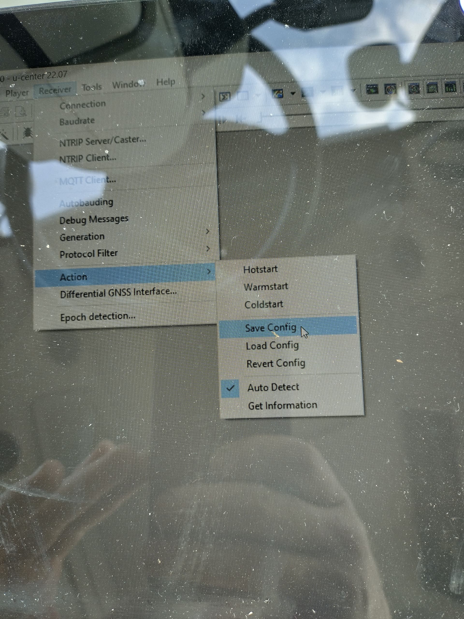
I soldered ampseal to another pcb and now F9P has 3.3V all the time. Still no GPS on AgIO. I’m I doing configuration tje right way?
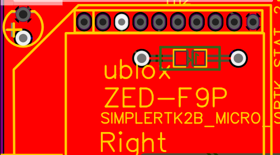
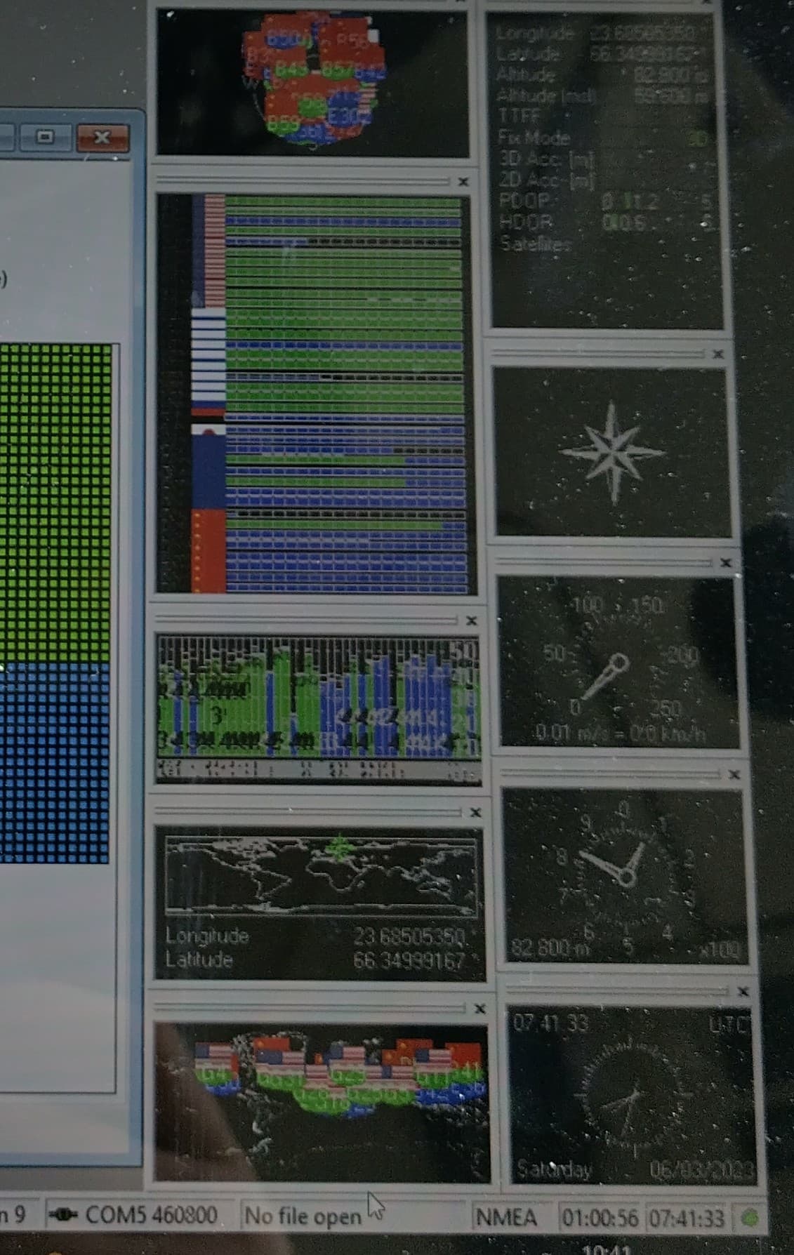
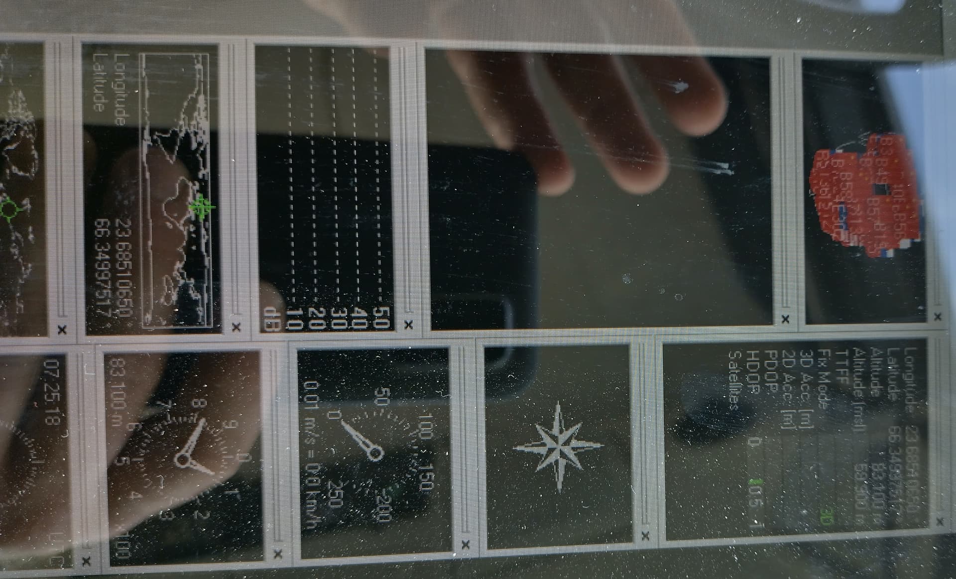
After i update firmware to UBX_F9_100_HPG132… .bin u-center looks like this
Now I have tested 2 pcb and 2 F9P micros and the result is still the same. I think it must be that I’m doing something wrong in configurating F9P. Are the files same for standard and micro f9p?