Just wondering what the best approach for connecting an IMU would be, if using RVC mode?
I’ve got BNO080s and also testing some WT901 and WT61 units, which can output a 100hz continuous data stream.
Should I use them as a separate IMU module and just send high-speed IMU data straight to AOG over the network, or should I try to incorporate it into the PANDA sentence?
@PotatoFarmer was doing it on the Teensy and putting it in the PANDA sentence. He found he could get the GGA sentence, then immediately get the latest reading from the IMU stream and it was close enough to work without any delay or reading the IMU ahead of time. The latency in RVC mode is much reduced as you don’t have to do any I2C polling.
Am definitely interested to hear how the WT units work out compared to the BNO.
I ported your PANDA RVC code to ESP32 (so I can use NTRIP with the F9P) and gave it a test run today. I drove with my Deere autosteer driving (RTK), and then just collected the PANDA sentences, which I then post-processed in python and displayed in QGIS. The results are promising. I am thinking about trying to collect the last 10 IMU readings for each GGA and then in my script trying different past readings to see if one lines up better than another. I think my post-processed path has a variance of about an inch, which isn’t really that bad, frankly. I think my dual GPS setup varies by nearly the same amount, as does the real Deere system.
According to QGIS the path would have been straight, yes. I was just collecting raw F9P GPS and BNO observations while Deere Autotrac drove (actually using the Agra-GPS unit), and put the numbers together after the fact. It’s handy way to test out things like filters as well. In this preliminary trial I did very little filtering. I will try some roll angle filtering though.
In Python I calculated the IMU heading offset using the VTG heading (with minimal filtering), and it was pretty constant. I can play around with different forms of heading filtering to see if that improves things but I suspect it’s not needed. The only open question is whether the IMU timing is close enough, or if we have to reach back in time a few milliseconds.
I did have some issues with the ESP32 just not spitting out any messages at all for several seconds from time to time. I suspect a UART buffer overflow, so I might have to pump the serial ports a little more often while processing in the handlers, especially since the ESP32 was doing double duty passing NTRIP data to the F9P from bluetooth.
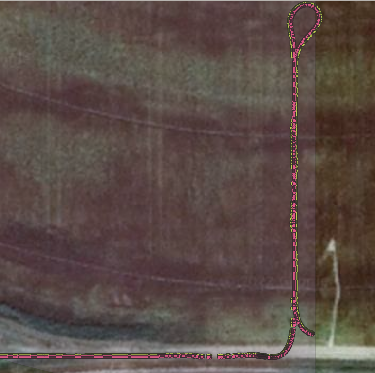
Here’s a little plot from QGIS. The yellow dots are the raw F9P GPS positions that came from the antenna mounted to the front right side of the cab (it’s one of the dual antennas I use with the PX 1172RH receiver). The pink dots are the corrected position that’s supposed to be the center of the tractor, compensated for roll. Looks okay although you can’t tell the deviations from this zoom level. I don’t think the field was very bumpy today (it’s all soft and melting), as the yellow dots don’t show a lot of wavering to begin with. According to my script the corrections from roll were typically about an inch. So I need to do more testing on rougher ground.
PS the google map image clearly shows what happens when you prime a sprayer boom with authority in it while on the field… the boom outline was visible until the following year. Now I have a recirculating boom.
Agra gps put a pile of testing into that receiver. It was cool to witness, made me believe that you did not have to be Samsung to develop electronics. Farmers are pretty smart.
That’s correct. I took that RVC Panda code and modified it. I removed all the dual GPS code and any remaining I2C code for testing purposes. I also have it spit out just plain comma-separated values instead of an NMEA sentence, which I can easily parse in Python, and also read directly in QGIS to visualize it.
I figure a good way to test any algorithm is to have the commercial system do the driving, where we know the compensation is about as good as it gets. Then I can collect data from another GPS antenna and also the IMU and try different filters and algorithms to see how straight I get the resulting plot.
Okay I modified the Panda RVC code on my test rig to always remember the last 10 IMU positions. So every time a GGA comes in, I log it along with the 10 most recent IMU positions to my laptop. Then using a python script I do the actual compensation calculations and spit out a CSV file with the adjusted latitude and longitudes that I can plot with QGIS to visually see how things are. Even if I just manually drive the tractor straightish the plot will still show if the adjusted positions are better or worse.
Tonight for kicks I tried using the 10th oldest IMU reading and it was noticeably better than the most recently read IMU roll. I hope that makes sense. I didn’t test the other 8 but I will. And I might expand back 20 readings just to see.
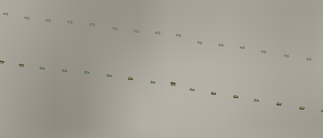
Here’s the plot. The tan arrows are the raw GPS position (antenna is the right corner of the cab at the moment) using the VTG heading for the arrow direction. The reddish arrows (most of which are covered by the green) are the corrected position using the most recently-read IMU reading, and the green arrows are corrected using the IMU reading 10 readings ago. The reason the arrows point the other way is that that is using the IMU heading and I was backing up the tractor at the time. The difference is about 4 cm in the worst case in this shot. This is with no heading or roll filtering at all.
Edit: I just plotted all of the last 10 imu readings simultaneously and it seems like #10 was best. I’ll try going back in time even farther next week. (pun intended). I believe the 10th IMU reading is the equivalent of 100 ms, so it’s possible with RVC there’s still some significant latency, but at least it’s trivial to account for it if you always keep the last few readings.
If your having to go far back in time to get the matching RVC reading that has already happened would that not mean that the latency is the waiting on the GGA?
You have also implemented my dream of swath direction recording. Would make nighttime combining much easier if we could get it in AOG!
The direction arrows are just a feature of QGIS where you can rotate a symbol based on the value of a field in the record. Since my data included the GPS coordinates as well as the heading, it was able to map that. So if AOG recorded direction somehow in the coverage triangles or in some other way I’m sure it could be displayed in AOG and that would be very useful.
As for the latency, yes the latency could be largely the time it took to make the GPS observation and create and send the GGA message. But I’m sure there is latency in the RVC measurement and transmission itself. I guess I’ve shown that we still need to take latency into account. But like I said it’s very easy to do with RVC just by keeping the latest x number of readings in an array. I just used an array of 10 items and then had an index that used modulo addition to wrap around. Reading #10 is just a matter of reading the position at (index+1) %10, so it’s fast and easy.
I’m of the same opinion as @PotatoFarmer, we can’t travel in time, the response delay must be in the GGA… if by anticipating the reading of the BNO we “go ahead” to measure the roll to compensate for the transmission time, it would mean that we would be trying to measure an event that has not yet occurred
I don´t see it that way.
You have an (old) GGA, then you want to take the Roll measured at the same time, so you go back in time and take/(pick) the (old) roll, hopefully measurred at same time as the GGA was measured at top of tractor with the GPS antenna.
Like torriem say about 10 RVC measurements back in time.
There is latency everywhere. It takes time to observe the satellites and compute the RTK position. It takes time to generate and send the GGA sentence. It takes time to measure the IMU’s sensors and generate and send the RVC message. All of it has to be taken into account. And regardless of how you count it up and where it comes from, the latency is about 80-90 ms from the appropriate IMU reading to the time you have received and parsed the GGA sentence.
Looking back in time is much easier than looking forward. The old Panda had to look forward because I2C is essentially a polling protocol. RVC is a push protocol. It’s always feeding us values. So it’s very easy to always keep the last few readings. That makes it’s trivial to go back in time. Here’s the basic structure in pseudo-code using the Adafruit library (Panda RVC has their own version):
#define BNO_MAX_LOOKBACK 20
#define RVC_TIME 10 //10ms between messages

Adafruit_BNO08x_RVC rvc; //actual RVC parser
BNO08x_RVC_Data rvc_data[BNO_MAX_LOOKBACK];
int current_rvc = 0; //always points to the oldest message

/* Look back in time lookback_ms milliseconds and get the
    index for that past reading. */
int get_old_index (int lookback_ms) {
    return (BNO_MAX_LOOKBACK - lookback_ms/RVC_TIME + current_rvc) % BNO_MAX_LOOKBACK;
}

/* regularly scheduled IMU processing */
void imu_update(void) {
    if (rvc.read(&rvc_data[current_rvc]) {
        //a new message came in
        current_rvc = (current_rvc + 1 ) % BNO_MAXLOOKBACK;
    }
}
It’s a very simply and fast calculate to get the index into the buffer of the older reading. The buffer continually circulates so there’s no need to move any data around. Also if Panda were to be modified to include all the roll readings, then how far back you looked for the IMU reading could be configured in AOG itself. Although I think once the ideal latency is found it wouldn’t ever need to be changed.
Tonight I verified that for me (using a PX1172RH in this case, not a F9P but it should be about the same) that from the moment the first bytes of “$GxGGA” comes in at 460800 baud, looking back 90 ms for the corresponding roll works the best for me. Actually taking an average of 3 roll readings centered on the 90ms mark seemed to work pretty, although I’m not quite sure that’s necessary. Both 80 and 100 ms were worse.
Maybe we can do like the first Panda, continuously reading the BNO, and then go forward from the last GGA sentence (10ms?) , store those BNO values and use them when the next GGA arrive