Using v2 pcb with aog v4.1.12
Running dual f9p with Matthias code. Tried to reload esp32 configs and tried to just go through USB hub. The button engage numbers in the serial line switched from 7,5 to 6,4. Thought is was a corruption caused by going through the hub. I connected directly to nano and reloaded ino, but still have the 6 and 4 when I toggle the steer switch. I unplugged the optocouplers and it went back to 7 and 5. Thought I had a bad opto, but if I put a new one in the implement socket, it goes back to 6 and 4. Will I have to replace the pcb ? 
Since this happened the autosteer is unusable, just wanders all over, with no help changing settings. Thanks
1 Like
Hi
If I understand the code right(but it’s 4.3.10), workSwitch will give a value of 1, SteerSwitch 2 and Remote 4.
Value is hi when circuit open I think.
So if you have 6 and 4 instead of 7 and 5 it is because the WorkSwich circuit is closed(shorted)
So I think Your right about checking the Implement opto, maybe remove the nano and check the pcb for shorts/bad components?
I think something is wrong with your pcb.
That would explain your problem with autosteer, it should work with 6,4. WorkSwitch/Implement is only for the Map painting on/off.
Thanks Pat, I think your right about the board. Was just hoping it was something simple because I soldered everything directly to a 12 pin deutch connector to keep from having any connection issues. Ironic ?
You should post a picture of your pcbv2. Pcbv2 normally do not fail. With pictures we can see if any component is put in wrong. With pictures of both sides we might be able to see bad soldering too.
I will when I pull it out. This board has been in this tractor since June I think. It is the one that gets all the changes as well. So far it’s been in 3 enclosures and 2 styles of connectors. I feel confident that it is probably where I’ve resoldered connections when I changed it. Odd that it worked for so long though.
So maybe not the PCB but the settings. You have uploaded your chosen settings from AOG to nano?
That’s what I was hoping. I reloaded ino with no change, then changed the nano with a new one, and loaded ino before installing it. No change either. Pulled steer opto, then implement opto, and that’s when the number went back to 7 in aog. I thought it was just a bad optocoupler, but now it wont hold the line, it just wanders back and forth across the line.
Something else also. In aog with dual f9p. When I turn on the end, the paint folds like a ribbon, or just gets real narrow. Implement width is correct also, but team lines were leaving about half a width between . I didn’t get a picture of it though. Was planning to fully uninstall aog and reload. This all showed up at the same time. It was all working well when I did that offset test for Matthias that I posted the pictures of. It was tracking east and west like a lazer. The next time I started it to finish sowing, and it was as described above.
But did you set the ino from AOG.
First load ino to nano from arduino ino, then set things right from AOG
Yes, I sent setting from aog, in module config and data sources to nano
And you did use the ino from the new 4.3.10 support folder
No I use this one
https://github.com/benreu/AgOpenGPS/tree/danfoss_proportional/ArduinoCode
I never got 4.3.10 to work usable with danfoss valve.
Am still very hopeful for a 4.3.10 modification that will work though.
Last correspondence with Richardklasens_admin, he was going to look at modifying code to work
Nice thing about this whole setup is, if my board is damaged, I can just build another. If aog is corrupted, I can just uninstall and reload.
Don’t have to send anything off for repair and spend all the profit off a crop to pay for it. That’s a Big Thank You to all of the engineers that developed aog.
All right, but then check if both 5v regulators on PCB are OK
Looking at the pcb schematic, one 5v regulator feeds led and WAS, and the other to the nano. I have 5v at all.
I sprayed urethane on the board after soldering for oxidization inhibition. Kinda looks bad, but out in the sunlight, I cant see any bad connections.
The blue relay is an opto relay, I used to send 12v to Udc of danfoss valve. Pwm2 energizes it. Pwm1 is pwm signal to Us of valve. Dir to md13s switches ma to mb, just to make sure no voltage to the valve without steer switch engaged.
Tested voltages on all 12v connections as well, and cant find a problem. I think I will completely uninstall aog, and reload and send to module, and see what happens.
In pictures I see there is nothing connected to workswitch or turnsensor (former Encoder), so it should not matter if you have optocoupler, or not in those two.
You use manual installed ino so you must manually set things right accordingly both in ino and AOG program (as AOG can´t upload to that ino)
Maybe you have set the relay setting to high instead of low (removed the tick in Active Low in tool settings for switches)
I took the optocoupler out ot implement to get rid of the 6,4.
This ino will configure from aog.
I uninstalled and reloaded aog completely including appdata. Now everything is working correctly again. Did an AB line drive test and it’s good.
Also the refresh rate above rtk was getting up in the 60’s, and now it’s back down to 10-18 like it used to be. Also noticed that GPS rate matches my f9p settings.
Thanks for the help. I’m pretty sure I would have changed the pcb, and been in the same spot.
1 Like
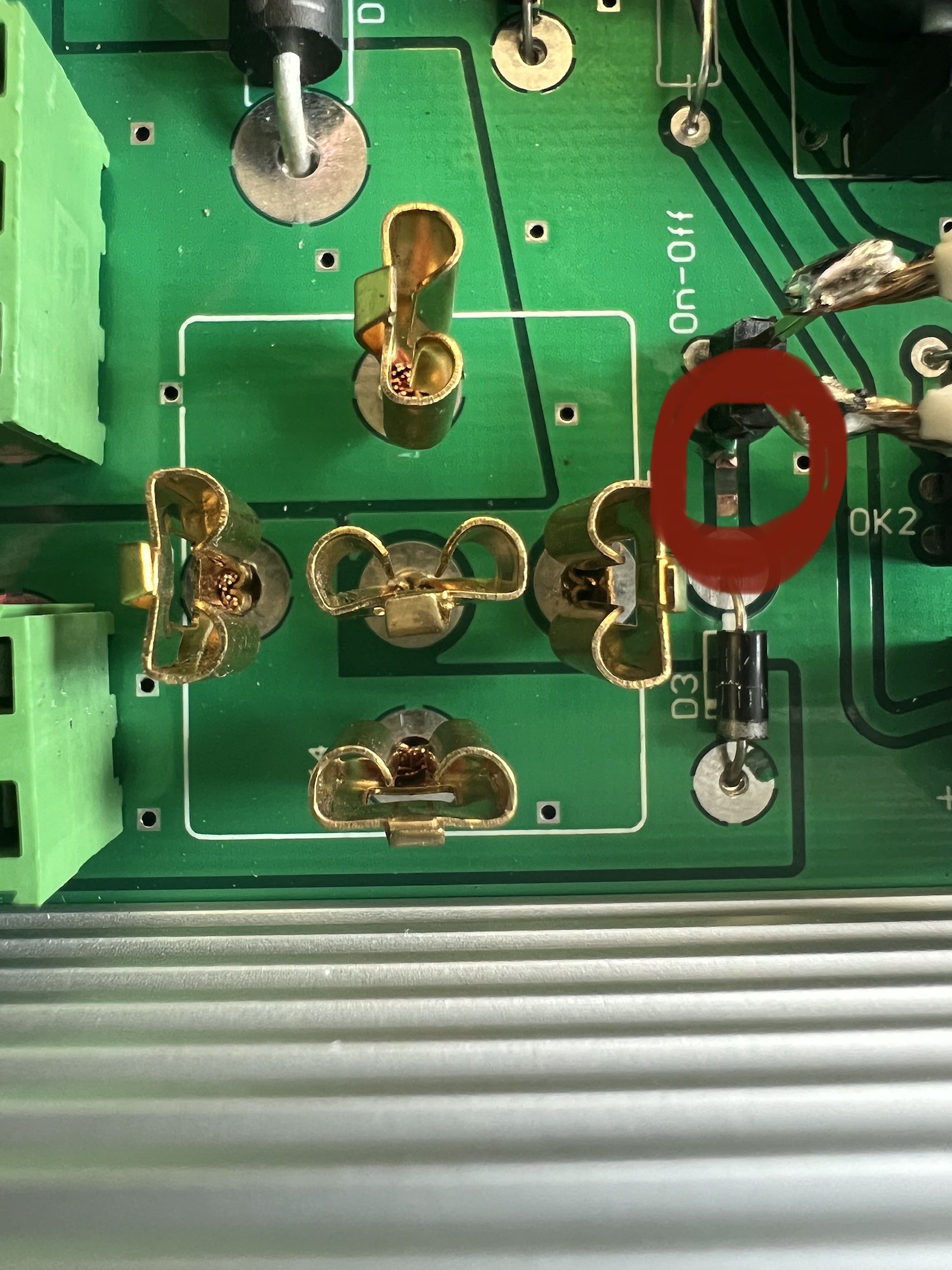
You have wrong polarity .batt is positive gnd is negative.
Thanks, yes that was right, still don’t get myself why would have done it like that.