Hello, do you think a 16 awg wire is enough to wire everything for the AIO PCB or should I go with a different wire size. Also, for the AIO PCB should the steer switch be a button or a switch and if button. with or without retention? Also if you have any recommendation for the relay/diode or whatever that bosch black box in the photo is I would be keen to hear them.
The way the motor in the diagram is wired I’d expect it’s a 12V motor but many people use a 24V motor which uses a 24V step up booster circuit.
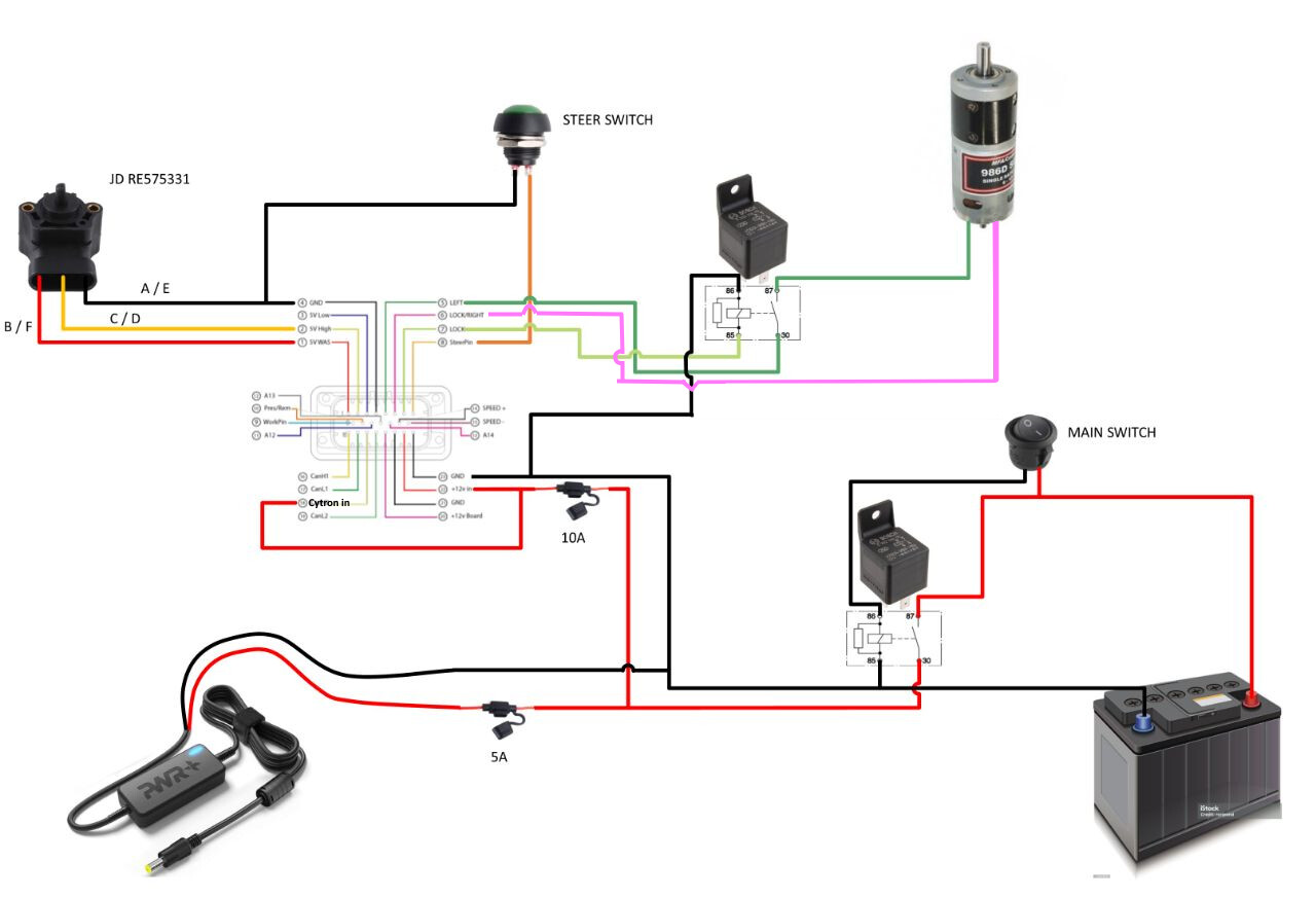
The Bosch device is a 12v automotive relay, you can use any 12V relay rated for your application.
In the diagram you posted, one relay is used to break the motor’s connections so that it can free wheel when autosteer is off. It needs to handle the motor’s full current. The other relay (being controlled by MAIN SWITCH) controls the tablet charger power (PWR+ device) and the main 12V power to the PCB which the diagram shows is also supplying the Cytron In (motor power) but I strongly recommend supplying 12V or 24V for the Cytron In through separate fused wired direct from the battery.
If you run a separate Cytron power wire, then 16 awg is plenty for everything except the Cytron power wire.
1 Like
Thank you