PCBV4.1 - build and test

Evening all

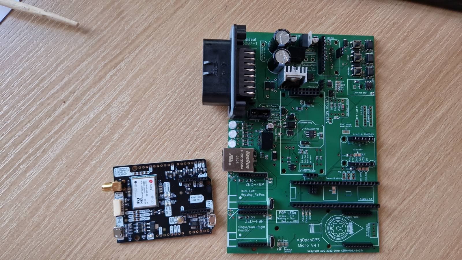
My PCB 4.1 (Micros) arrived, so time to test them. Thought I’d document the process just in case it helps anyone.

I got lucky and JLC assembled all - I did remove the headers for Teensy and BNO/IMU from the build as they weren’t too great on my assembled PCBv2.4 and I didn’t want that hassle again.

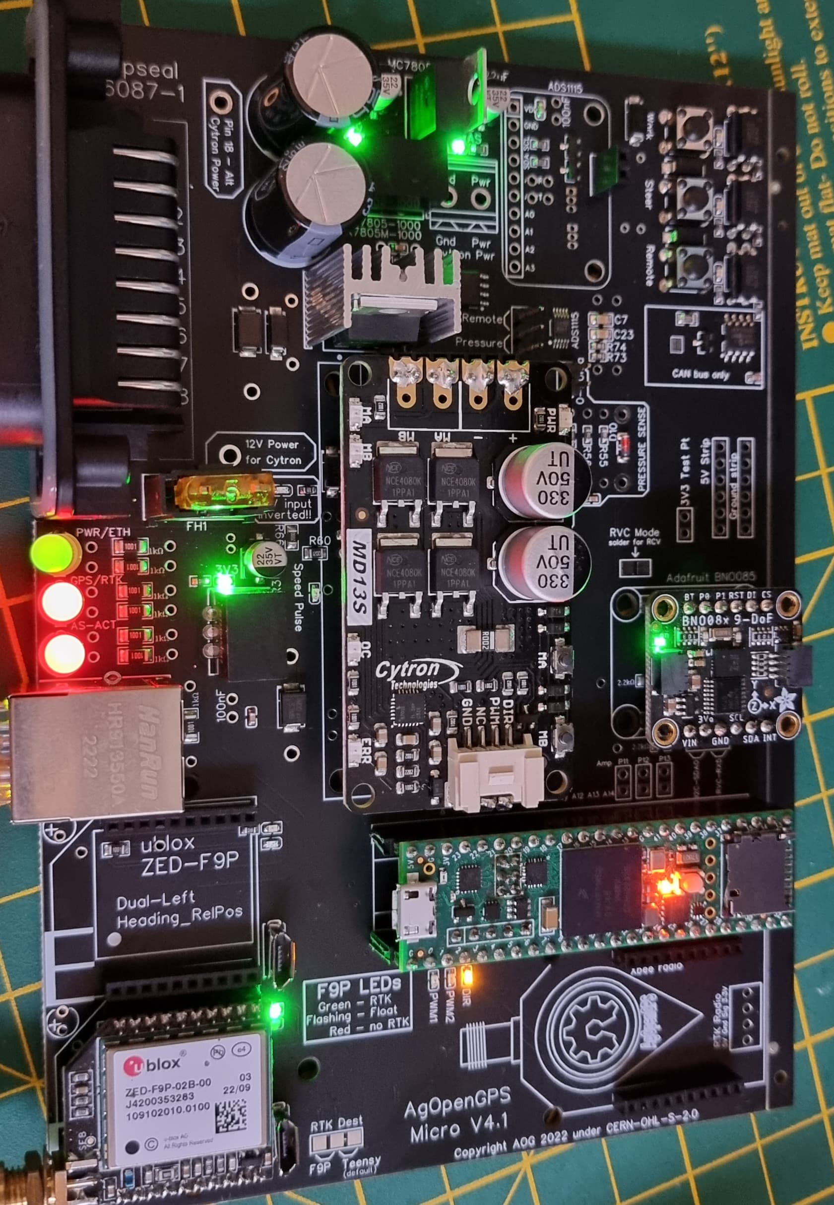
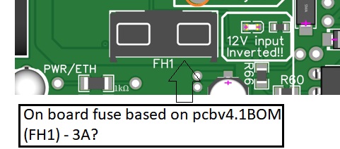
First, a visual check to make sure everything looked OK, no damage etc. There were no apparent faults and the all-important voltage regulators appeared to be the right way round, so I connected it to my test bed, inserted a 5A fuse (smallest I could find) and powered up gently. Straight out of the box, this is what I got:

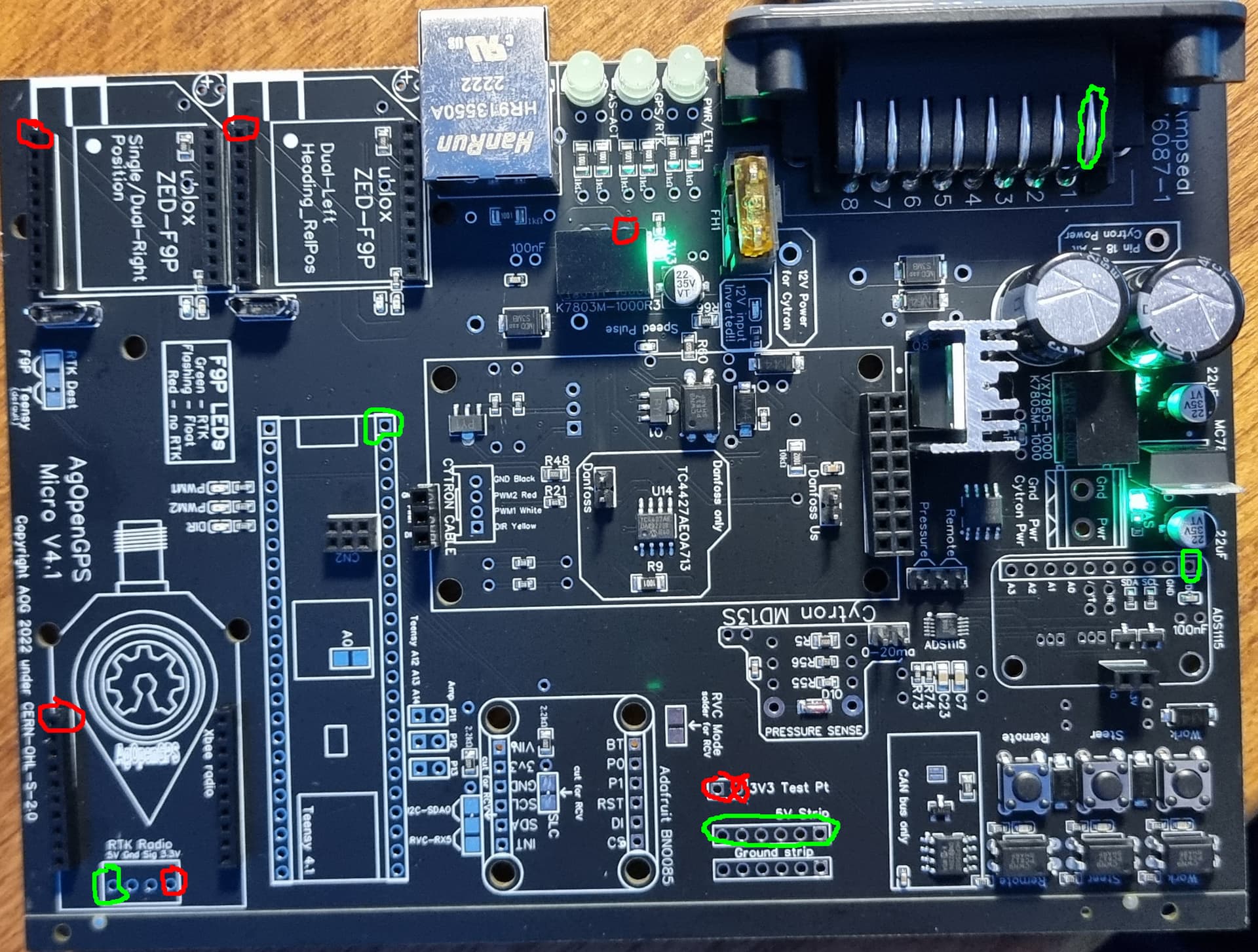
As you can see, there are a couple of LEDs lit up already. The green and red annotations are where I put my test probes to confirm the all-important voltages going to the expensive components. RED is 3.3V, GREEN is 5V. As you can see, the hardware team did a great job and also put some handy probe points in, and LEDs to show all was well. But, you can never check enough - especially when F9P is so expensive. So before you connect anything, sort that out.

All appeared well, and so I soldered my headers for Teensy and IMU on - all good. I knew only 5V was going to the Teensy, instead of anything more accidentally-serious, so I was confident to plug that in.

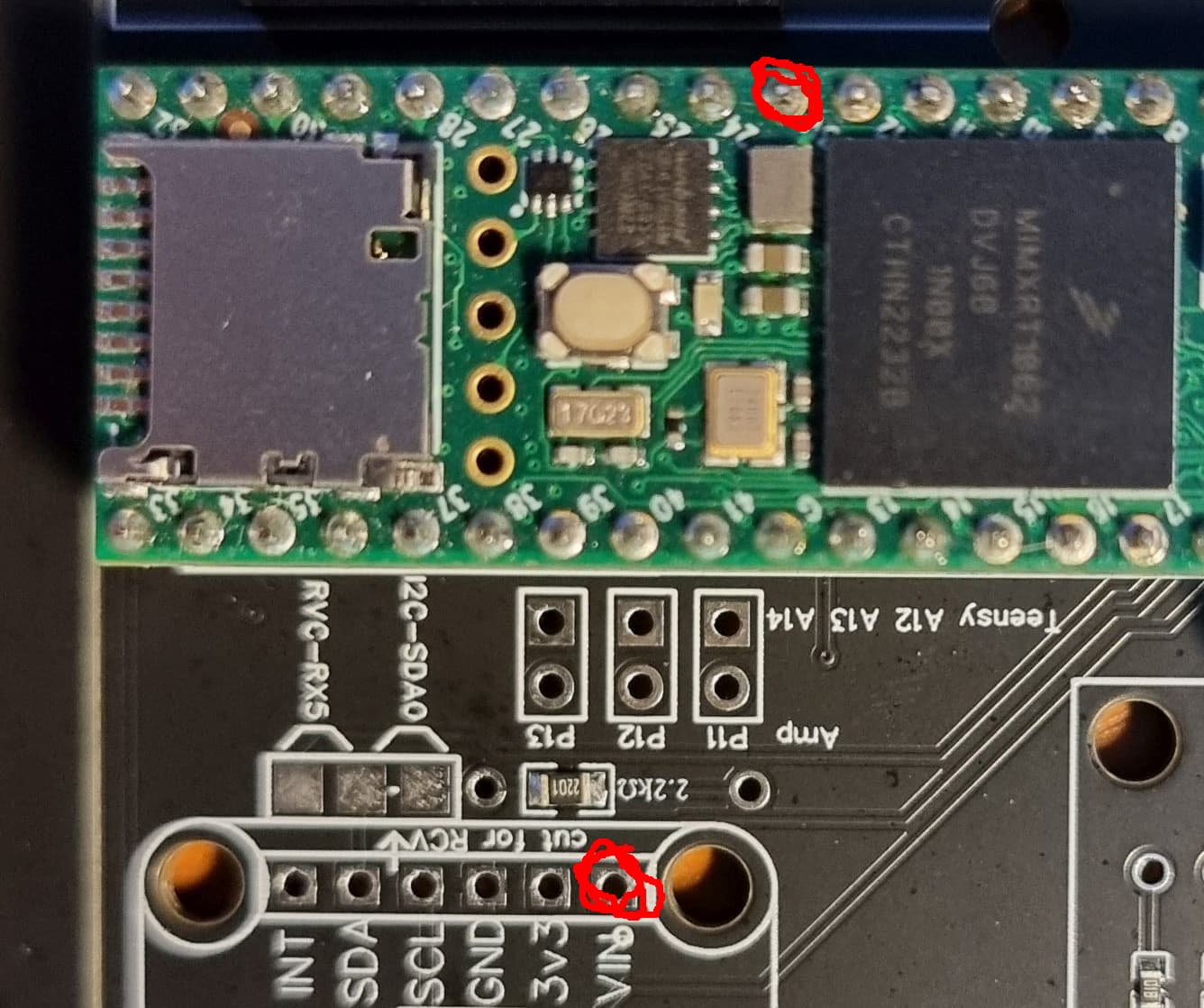
Now, with Teensy there, it supplies the IMU with 3.3V, so I checked I now had only 3.3V going to the IMU input from Teensy (in red). All good. Time for the IMU.

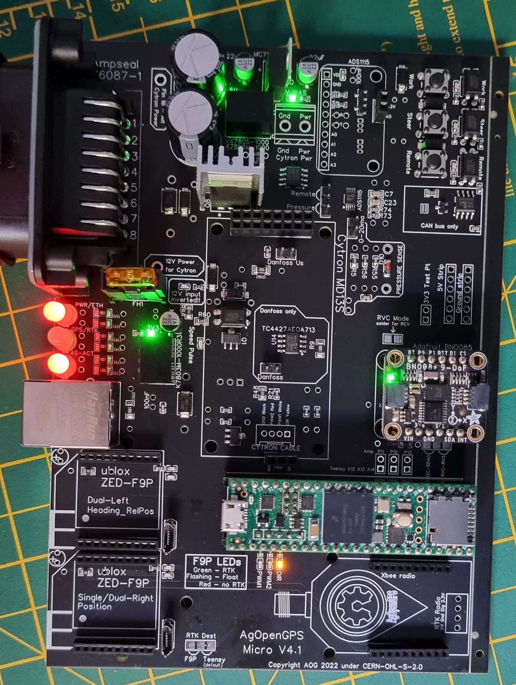
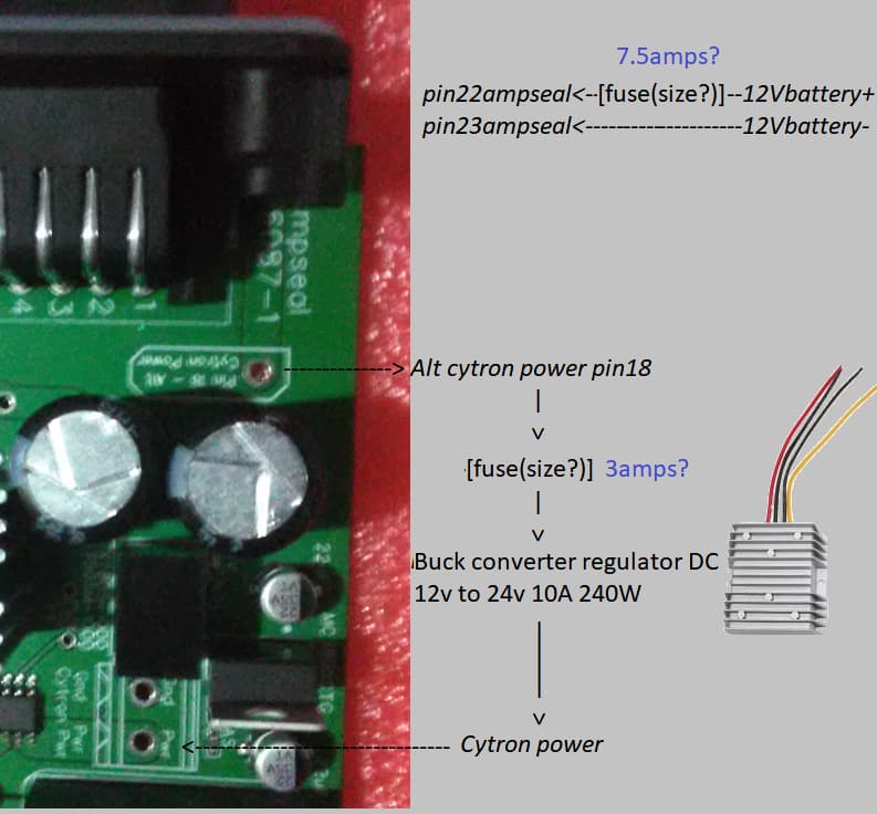
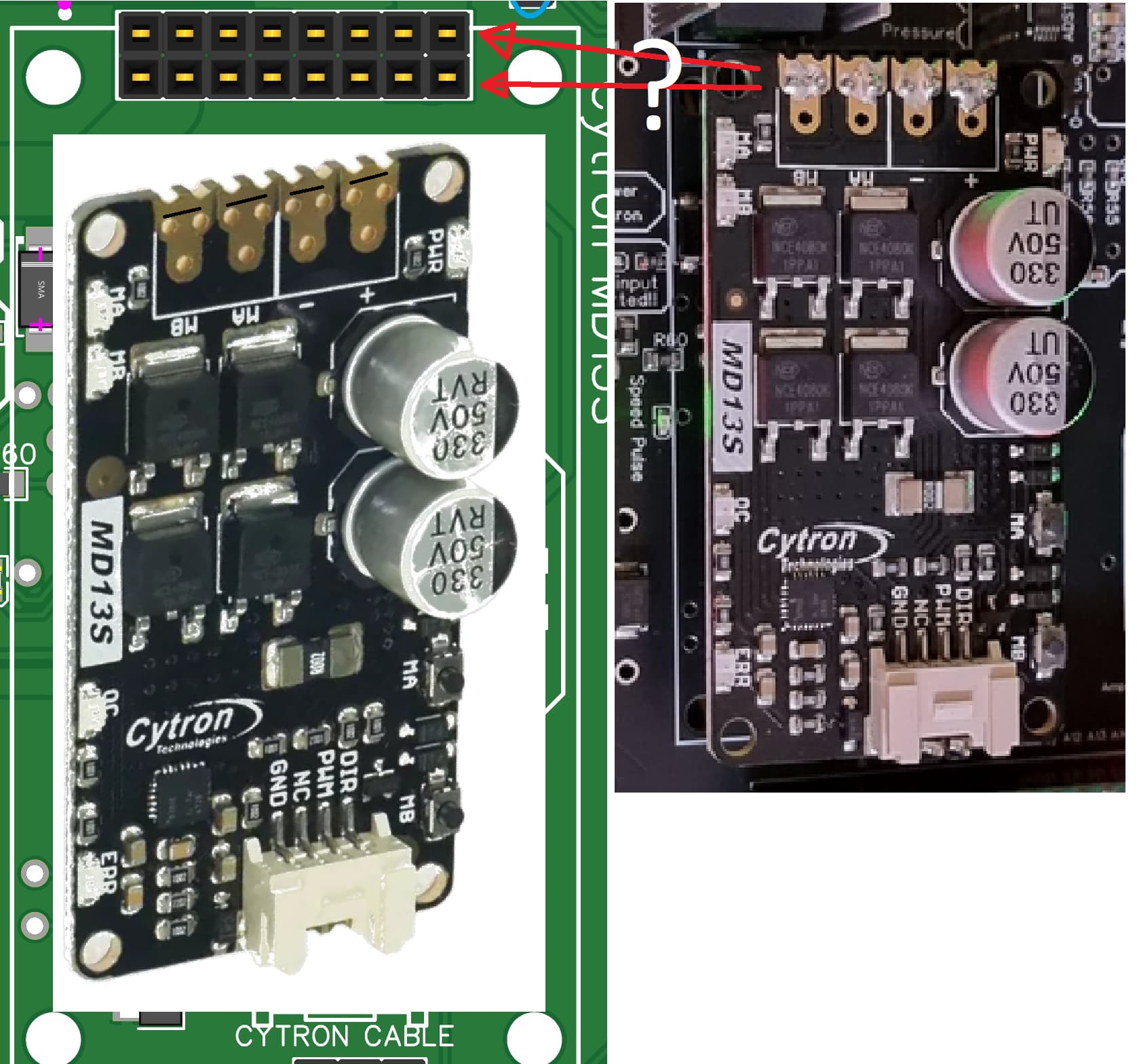
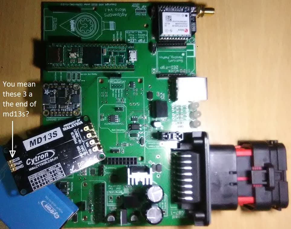
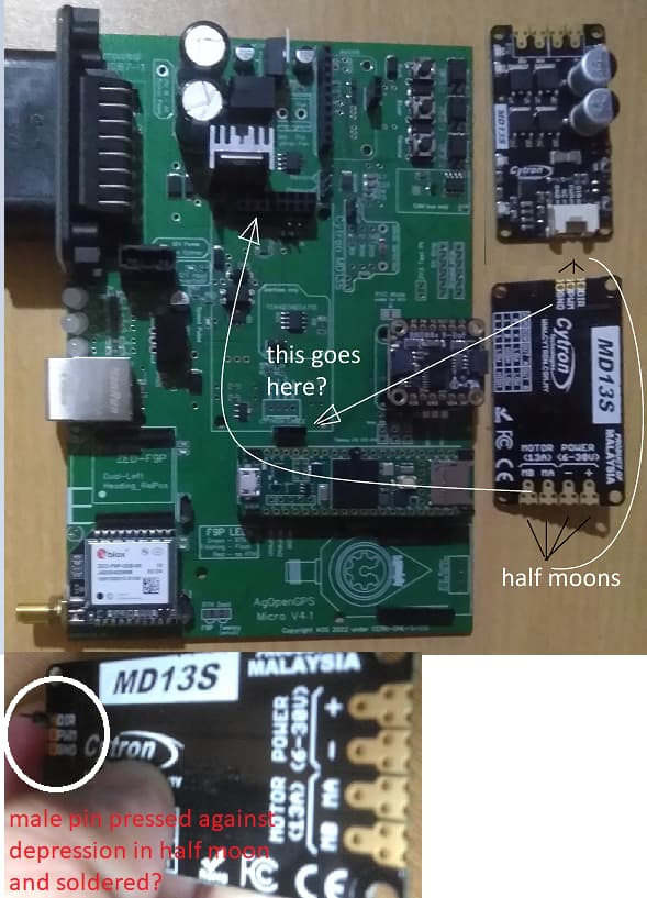
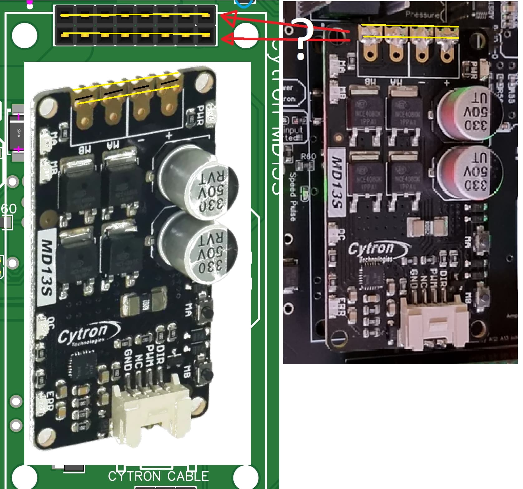
Teensy lit up the IMU, so progress. Now, add the Cytron. This was low risk as at the moment, I don’t have an input selected for it (I’ll use the standard 12V for this as that suits my use case):

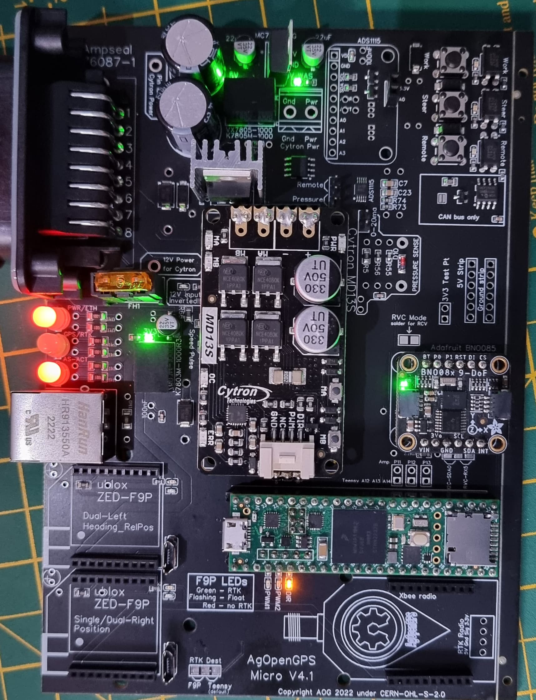
And with that on, I added my F9P, connected ethernet up and … we’re good (photo taken just as the board achieved an RTK fix) !

13 Likes

Nice guide! I will like to see this guide in the Wiki :slight_smile:

For AiO 5.0 board. Maybe expose the testpoints on the board so we dont need to probe in the headers?

2 Likes

I would still test the headers, personally - but yup, will add to the wiki.

1 Like

Hi, looks like I have a problem, I have bought AgOpenGPS Mico v.4.1 pcb and simpleRTK2B – Basic Starter Kit, which are not compatible in simplest way? Anyone has this fail? how solve this?

1 Like

Buy yourself another f9p but the micro version and use your standard f9p and make yourself an rtk base station

1 Like

Hi Andyinv,

Can you provide additional images of your excellent post showing sections of the pcbv4.1 where power is/are provided and the input voltage. I am new at this and the posts I’m able to read through so far somehow didn’t show this basic aspect of the AOG pcbv4.1. Once input power is provided that’s when relevant led lights up and I can proceed with checking output voltages, right? Thanks.

Many thanks.

Ah sorry, supply 12v to pin 22 and gnd to pin 21 or 23 on ampseal connector :slight_smile:

Basically, supply the power the board will need in its typical usage state.

Can you take a look at the attached image and confirm if fuse placement is correct. What’s the fuse amp you used for the two locations needing it. Obviously the board is 4.1micro and the electric motor is going to be 24v.

Appreciate the reply, thanks.

TeddyStamford indicated “I’d fuse the 12v going into the converter at 7.5amps, or the 24V coming out before the PCB at 3amps”.

So in my graphics it means pin22ampseal fuse will be 7.5amps, right? If the graphics is right, 3amps fuse will be placed on the wire soldered to Alt cytron power pin18 on the pcb right before the current enters the buck converter? Response will be much appreciated, thanks.

If you look in the v4 micro thread i think people are using a 2 or 3 amp fuse on the board itself.
There is also a video of what the phidgets motor draws at maximum speed at headland turns if you can find it but feom memory i think a 7.5 amp fuse is fine for that.
Id also fuse the main power cable going to your switch to turn the pcb on and off. Again a 7.5amp fuse.
You cant have enough fuses in place. I had problems with my v2.5 board and cooked it, the 2nd time i added i think 6 inline fuses on different lines, the main feed cable. From the switch to the pcb, one on the relay to the phidgets motor, one on the converter line, one on the steer switch line, even put one on the earth wire for good measure :sweat_smile: Simple and cheap to install . Think i used 5amp fuses for most of them. Start small and if they blow investigate the cause. When you start cooking the major components it gets expensive

I’m really apprehensive on powering the board due to accounts of board component blowing up so appreciate the redundant fuses you put all over your board. If I may have your indulgence, I made notes on your comments to help me visualize where to place the fuses:

  1. If you look in the v4 micro thread i think people are using a 2 or 3 amp fuse on the board itself.
  • When you say on the board itself, that’s the FH1 section of the board?
    on board fuse
  1. There is also a video of what the phidgets motor draws at maximum speed at headland turns if you can find it but from memory I think a 7.5 amp fuse is fine for that.
  • TeddyStamford did confirm based on his tractor experience about the maximum draw and settled on 7.5A. So, I will place a 7.5A between the Alt Cytron Power pin 18 → 7.5Afuse → step-up converter instead of Alt Cytron Power pin 18 → 3Afuse → step-up converter?
  1. I’d also fuse the main power cable going to your switch to turn the pcb on and off. Again a 7.5amp fuse
  • This will be the current placement in my graphics except that I did not use a switch. So, modifying the graphics, it will be battery + → switch → 7.5A fuse → ampseal22, right?
  1. You cant have enough fuses in place. the 2nd time i added i think 6 inline fuses on different lines,
  • the main feed cable: so number 3 above will be modified into battery + → 7.5A fuse → switch → 7.5A fuse → ampseal22, right?
  1. one on the relay to the phidgets motor, one on the converter line, one on the steer switch line, even put one on the earth wire for good measure Simple and cheap to install.
  • So, if I implement your setup, that will be Alt Cytron Power pin 18 → 5Afuse → step-up converter → 5Afuse → Cytron Power +?

Looking forward to your reply and thanks! Appreciate the insight and getting a little comfortable to energize the board.

For testing. 1a fuse on the board. That’s enough. All those other fuses mentioned are for drivers and outputs, eg cytron. Put a 1a or 2a fuse on the board, and work through the guide above.

You’re overthinking this at the moment, do the basics first.

Alright! So, that’s 1A or 2A on the FH1 of the board. Thanks.

Hi andyinv! Successfully tested the board for 3.3v and 5v just like you did. I just received the md13s, bno, gps and teensy. I can figure out how the bno, gps and teensy gets connected to the board. However, i can’t seem to figure out how to connect the md13s to the board. There’s two horizontal rows of headers at the top portion of the board containing eight section each. The motor controller has 1 single row of 8 positions. In your images you soldered in groups of 2 (i.e., 1 and 2, 3 and 4, 5 and 6 then 7 and 8). Which row in the board did you mount the motor controller. The first horizontal row or the 2nd? Thanks.

Hi, the pictures above show the BNO and Teensy fitted.

For the cytron, fit the 3 at the end first, then it will be obvious how you do the other end.

A

Thanks A,

This is how my board look right now without being powered but I know the result of the 1st step of checking voltage at various points went without a hitch! I need to solder all the needed male headers so I can proceed with the steps you outlined above. I got everything figured out once I have the header soldered relative to positioning on the board. Unfortunately, when it comes to the md13s, I do not know how to proceed after I solder male pin headers on it. When you say fit the 3 at the end 1st, you mean the one in the picture? Thanks.

Not sure on the latest aio boards but on the previous ones you soldierd the 3pins on the cytron on the very end onto the little half moon notches, and same the opposite end. But see what lines up on your board

Hi del_boy! Thanks for the assistance in figuring out md13s placement. Yes there are half moons at both ends of the md13s with 4 on 1 end (marked MB, MA, - and +) and 3 on the other (marked DIR, PWM and GRD). So in terms of soldering, male header pins will be pressed on the notches of the half moon then soldered, got it. I know you’re not familiar with pcbv4.1 but probably somebody else will be able to assist. So is the indicated position on the board to receive the pins soldered to the notch on the md13s correct? Thanks.

@rogerix Two rows of pins

Got it, thanks!