On std/micro and single/dual F9P, and the possibility of having one single board design going forward, one single design that could support both standard and micro F9P. It would be helpful to get some feedback on this please?
What board and F9P configuration do you mainly use?
Standard board, single F9P
Standard board, dual F9P
Micro board, single F9P
Micro board, dual F9P
0voters
If you answer that you use Dual F9P on a standard board, and a new board were to be released where the only option for dual would be Micro F9P, would that be a problem?
A board which did not support dual F9P standard would be no interest to me
A board which supported dual micro F9P, and single standard F9P would be fine
Ideal AiO board have um982 slot. As its better and cheaper then F9P. Can be used as single or dual gps. As more people use it configs become better and it can be f9p killer, I whould not build F9P boards if um982 was supported.
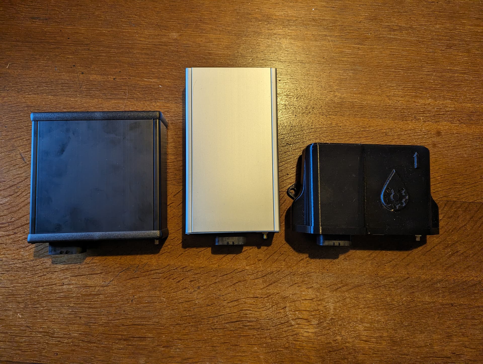
I don’t think the Micro gives you that much smaller PCB enclosure in the end. The Std is narrower and fits better beside tractor seats I find.
The standard has a USB so doesn’t need one on the PCB, which break to easily.
The Micro, when attaching the antennae cable, if you do it to tight you can twist the F9P out of its socket, the Std with a fly lead has no such problem.
No need for 3.3V voltage regulator with Std, that has been prone to incorrect mounting, frying the Micro.
Easier to repurpose a Std as base station.
Standard cheaper to buy and readily available.
I’ve made more Micros than Std but prefer Std for reasons above.
Yes, but pins don’t match exactly. Only first uart is match. And will other pins couse unwanted effects?
For AiO 4.x std I whould cut all pins and only solder vcc, gnd, rx1, tx1 on pcb headers if needed.
But bynav/um982 socket whould convince me to consider smaller boards. I think 2x micro, one standard f9p and bynav slot should be posible to be on one board in same space. Solder headers for what is your use case.
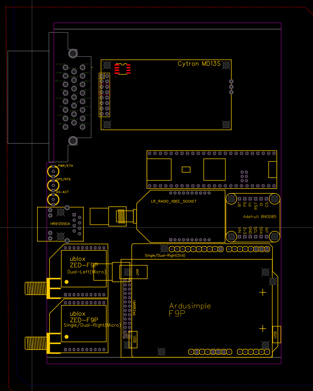
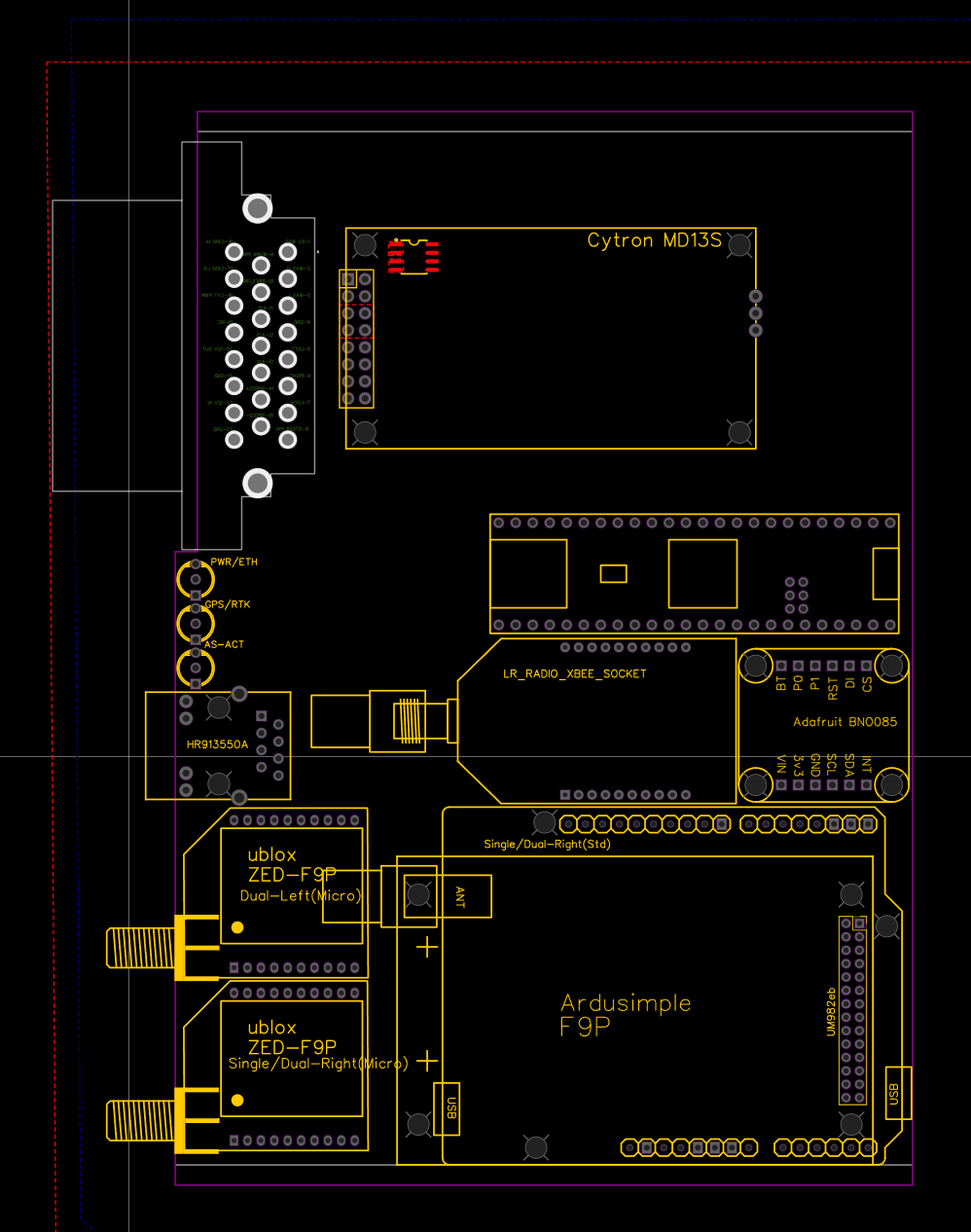
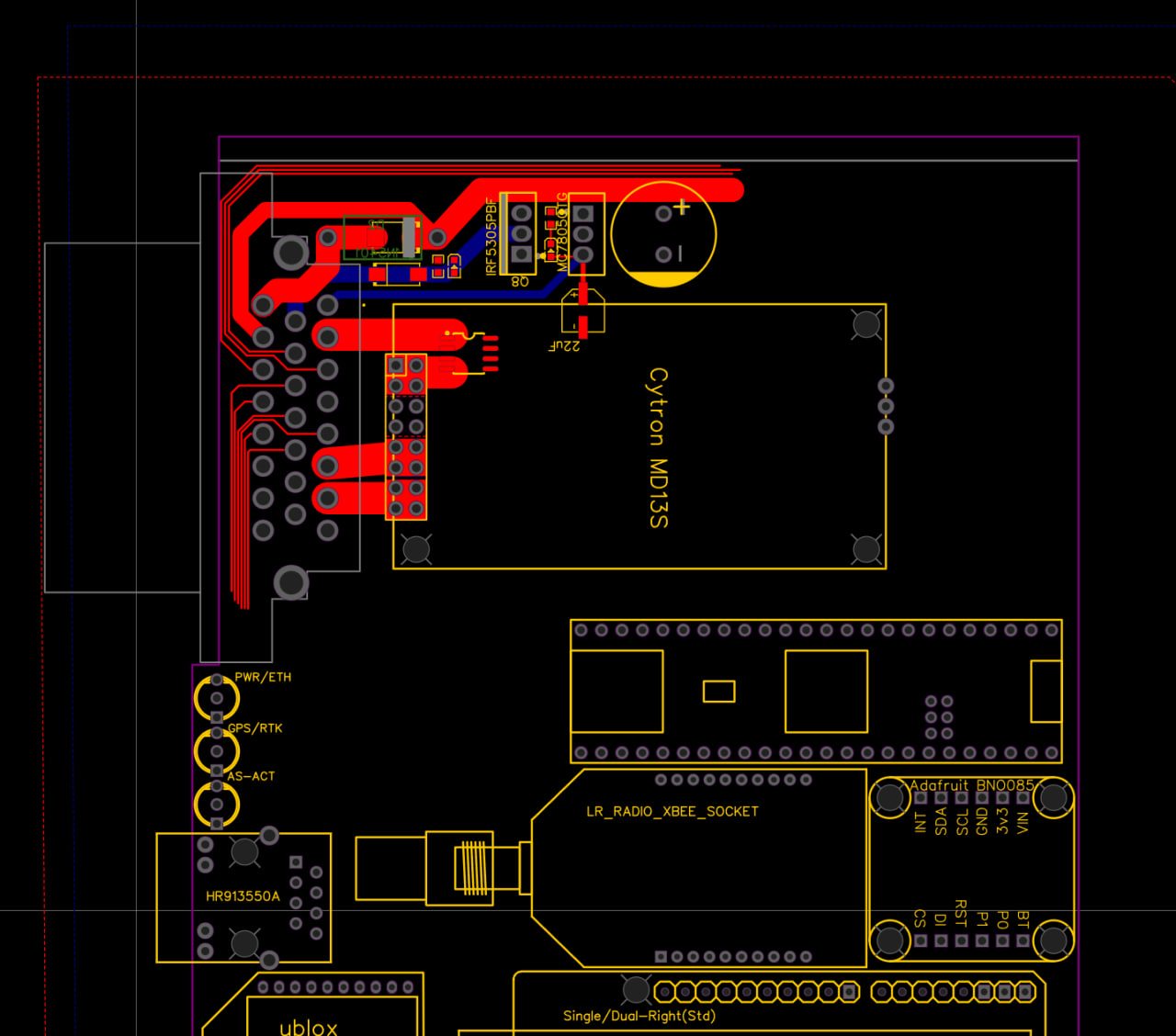
This is the layout I’ve been toying with. It’s the same Micro PCB size and faceplate layout.
Dual with either 2 Micros or 1 Std & 1 Micro or UM982/ByNav.
Single with either 1 Micro, 1 Std or UM982/ByNav.
The Std, UM982 & Xbee would all need RF jumpers.
Do you think there’s room for all the rest on the PCB?!?
The UM982 could possibly be rotated. I have not mocked up RF jumpers for it.
The AIO is designed to be able to be ordered fully assembled. JLC is the easiest for that. JLC never has BNO stock, their inventory limits design. BNO is the best IMU tried so far.
There are import/export laws related to IMUs that make import/export difficult. They can be used to build missiles. The way it is now, the individual web shop retailers have to handle that. Here in Canada it can even be difficult to order a BNO from some US web shops.
The IMU is a costly component and it seems every year there are multiple new boards to try. This way you can move the expensive bits from board to board.
The IMU isn’t required for dual designs.
The IMU is probably the most volatile hardware in AOG. Every major change in the last few years is somehow related to IMU.
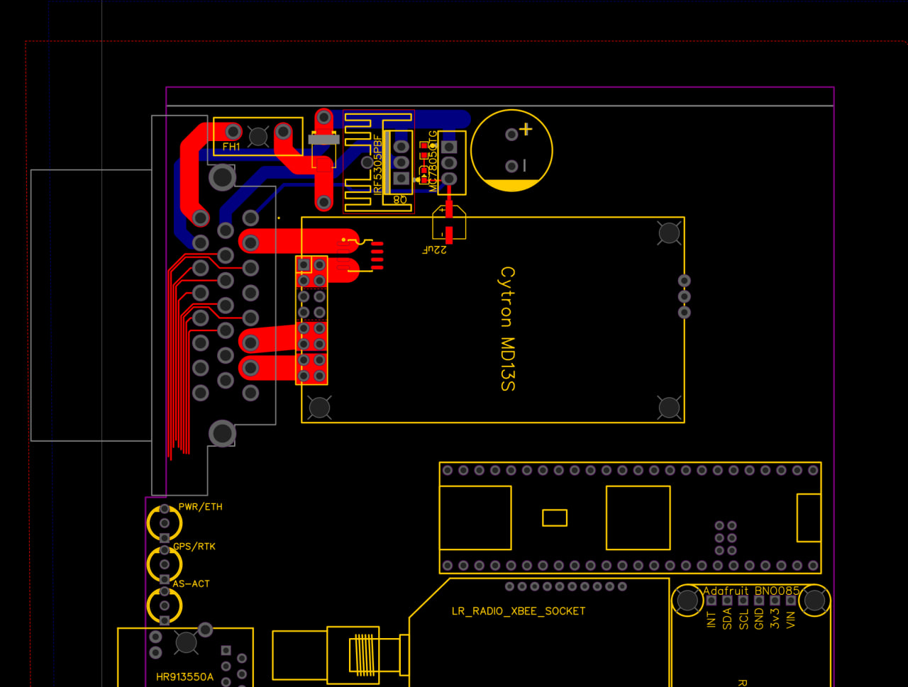
But maybe WORK/STEER/REMOTE should run around the top to put the optos/buttons in the top right corner again. Also, maybe the fuse should be external and do we need the LOCK fet’s heatsink?
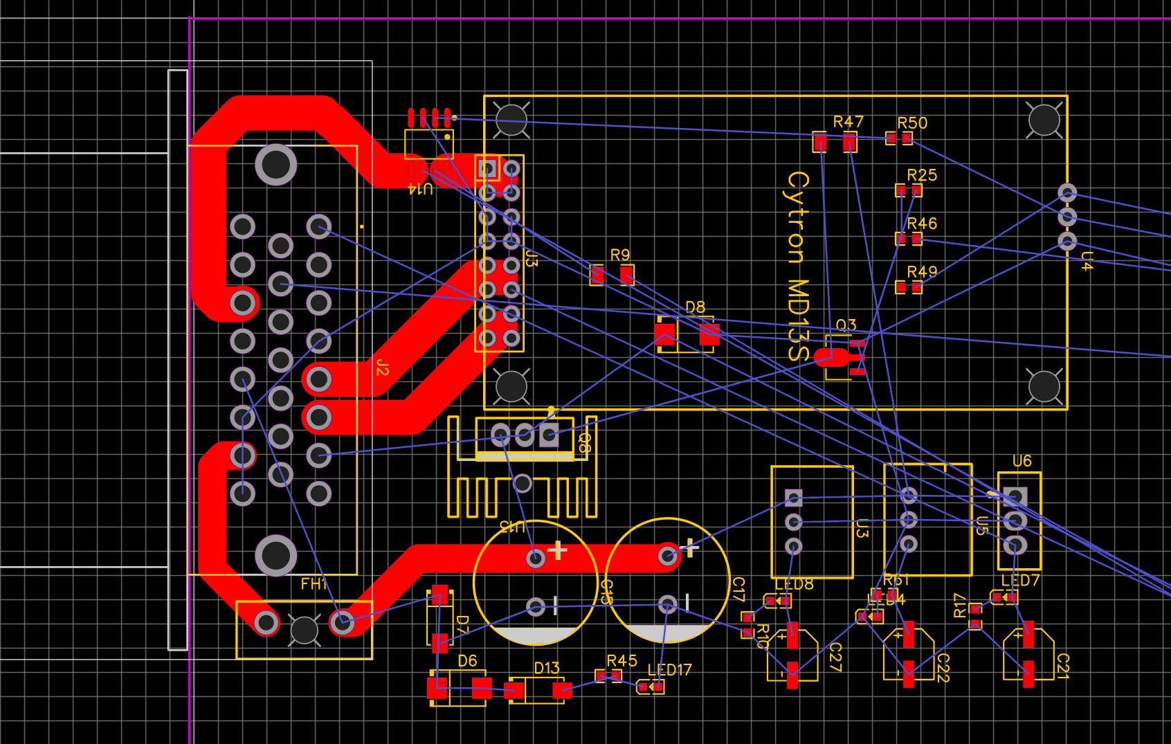
That looks nice. Is their any reason we can’t place the power regulators/supply section below the cytron? I think it would make routing the high current traces a bit easier.
Fuse on the board makes for a very tidy cable install… But if your board is tucked somewhere out the way, maybe having it external and more accessible makes sense.
I haven’t thought it through much further other then I want the power regulators close to where the power is needed, using longer 12v traces instead of long 5 & 3.3v traces. The Cytron could probably be at the very top.
If anyone is interested in playing around with ideas I can upload the easyeda files or share via a link (I think).
If the ampseal won’t be compatible with the current one why not go with AMP 35 pin?
Also Deutsch DT is MUCH easier to work with.
This box is sligthly shorter than the current STD board.
If pins are a concern we could have 2 connectors at both end. (I think STD has plenty of footprint to fit all sort of modules)
Although it would also make sense to have a daughter board with just a GPS + IMU + ESP32 which could be used as light bar over bluetooth / Wifi or via Ethernet (maybe even PoE idea of @PotatoFarmer )
as the design is available I think the whole ESP32 could be integrated to a PCB and we could have a dedicated navcontroller. Steering, etc could the live anywhere in the cab.
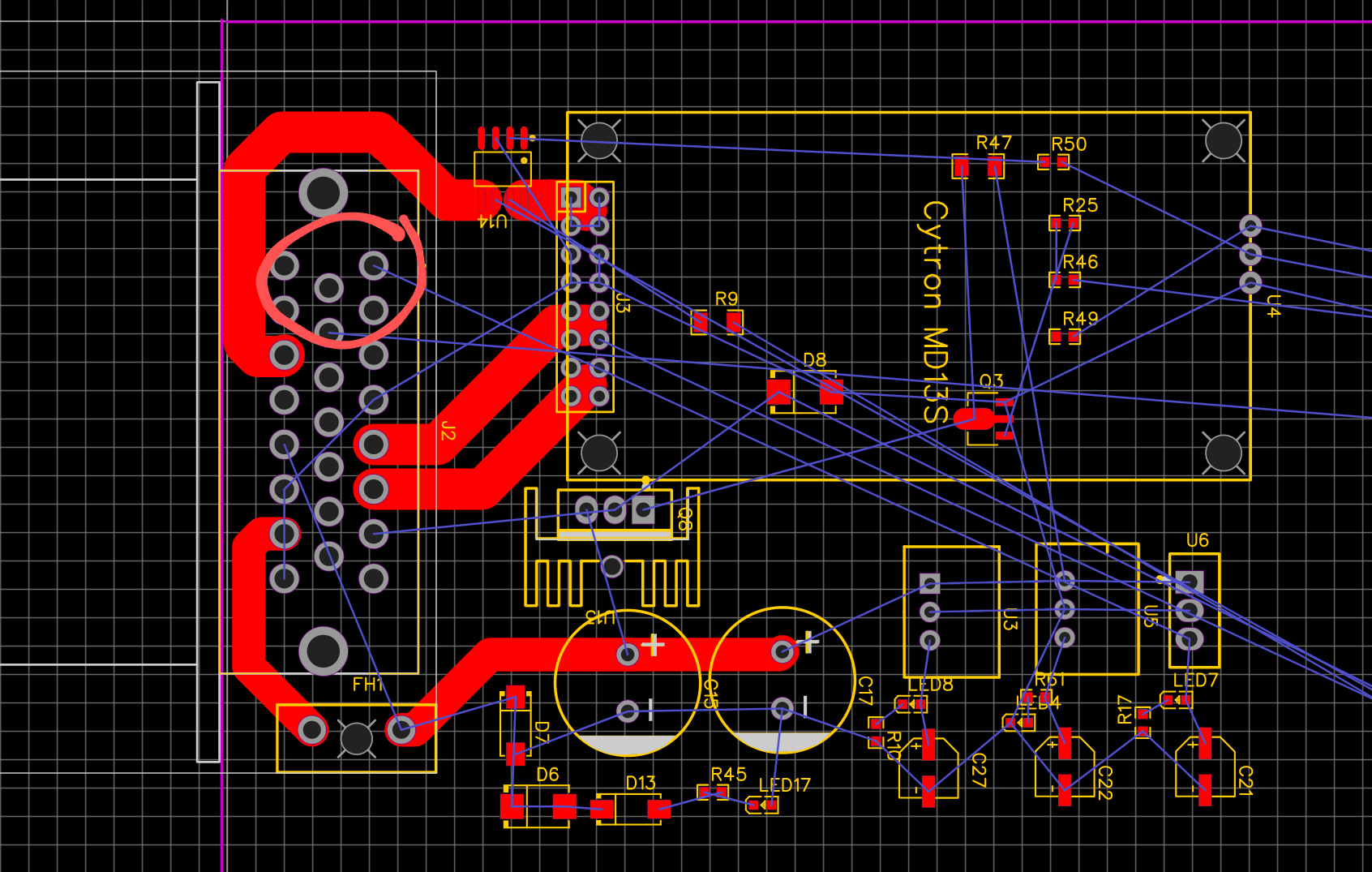
I was thinking of moving the cytron to the top like this and placing the power regulators below it. This way we can maintain the same pinout as before while hopefully making it easier to route the high current traces. I think we should even be able to route them on each side this way and with 2 oz copper we could get some fairly high currents.
Also is there any reason why UART1 was not used on the previous boards? And I was thinking we should make it an option to route a second or even a third CAN port with pin 19 which is unused and the 3 pins that go straight to the teensy. We could add three rows of headers and use jumpers.
I didn’t think it was an issue to repin the amp23 (it’s pretty easy) but keeping the pinout is doable except routing these pins is difficult if the Cytron traces are double sided.
I’d like to set some expansion/daughter board footprint under the Cytron for extra canbus like you mentioned. The thinking being that if you need the extra canbus then you’re not using the Cytron.