Ethernet switch is a must for section control or pcbv2+panda system, as 2/3 cables need to go to tablet, cheaper then router.
1 Like
The thread I linked to was about WiFi not wired Ethernet.
1 Like
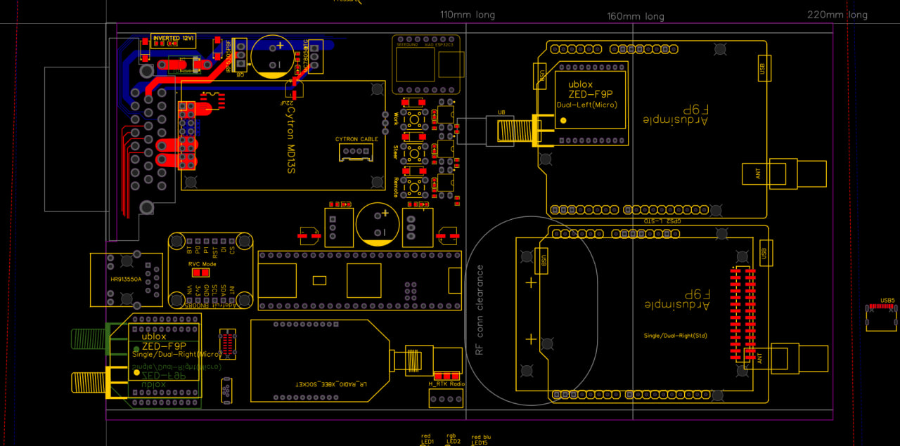
Here’s the latest brain storming idea.
This is the standard PCB width, in three lengths (1/2 full length, 160mm & full length 220mm)
There are enclosures in 160 & 220mm lengths
Supports dual micro in short length with one micro on bottom (requires soldering bot micro headers yourself to avoid 2-sided assembly by jlcpcb), also 2nd micro on top in medium length, and dual Standard/micro combo & bynav/um982 in full length.
Includes the idea/option of using a esp32 Xiao for wifi AP (ext ant).
1 Like
Looks very nice. I like the placement of the micro’s on the front, clever idea.
I was just thinking if it would be a good idea to add some sort of connector to the board for faceplate LED’s. I know those PCB faceplates seem to be gaining in popularity and it would make it very easy to have connectors already there. Could even get the faceplates assembled with the connectors and the backwards SMD leds already assembled so all you need to do is plug in a cable.
You mean just a pin header somewhere close to the faceplate? Which signals?
There’s room for 6 right angle smd LEDs under the top micro, we found some RGB and bicolor that are the same size as single color ones so that’s already quite a bit of blinky blinky.
One idea for front panel GPS RGB:
Solid red no data
Red blinking data but no RTK
Grn blinking float
Grn solid full rtk lock
Blue flash rtcm data
Any spare pins for bluetooth adapter? Might be handy to interface any cool little boxes (like an LCD screen on the steering wheel ![]() )
)
If esp32 with Bluetooth…
ESP32 XIAO footprint above the Work/Steer/Remote switches, which by the way, I’m hoping to change the work and remote to analog inputs. Remote already had the option for analog Pressure but this would be without any jumpers etc.
2 Likes
Here’s another idea. This is as narrow as the Std, but as short as the Micro. So existing Std guys can cut their 220mm case in half to get two 107.5mm cases. Switching to amp35 forces a repin so we can rearrange the pins as needed and there’s enough pins then to dedicate for all 3 can bus, rs232 nmea, speed pulse, etc. Could even double up the Cytron pins. Everyone can use their old harness and amp23 pins, just needs a new connector housing. I think putting the buttons under the IMU is best instead of by the ethernet. There’s a 4th btn shown for manually triggering PWM2 (cytron freewheel mod & Lock output). The Xbee is the only module on the bottom, close to the Right Micro, otherwise everything is on top. The Dual Std guys would have to split up their Stds and pair with a Micro, or get a UM982 instead for the same cost. Trying to get all the usb out the back side you just remove the back plate to update/program anything (except ESP32) so F9P Micro USB could be flat style (like Teensy has) under and beside the teensy (pcb needs notching a little for that). I also found other vertical micro usb that appear easier to solder and maybe sturdier then what we’ve used until now. The GPS modules are supposed to be placed so that the SMA jumper cables work with either right angle or straight connectors (only the Left Micro under the Right Std would need a straight SMA) and we’d need to leave space by the UM982 RF connectors for them to loop up/out and towards the faceplate, probably need to be long enough to loop towards the back, then up around to the front.

Can anyone see anything that’s obviously a show stopper besides trying to cram in all the other parts yet? ![]()
@Guy1000 @MTZ8302
2 Likes
Looks good - are buttons really needed tho? Beyond initial setup, are they ever used again?
I’ve been playing with building a little stimulation-board (something you can plug in to the AIO and it provides outputs for CANBUS/terminals etc for you to test on the bench with), maybe that might negate the need for buttons on the actual board? Does seem a waste of space for something so rarely used.
2 Likes
Maybe add at the ADS / WAS input the possibility to add a voltage devider and an tension burden. So it is possible to use a 0-12V sensor or a sensor with current output. Maybe use a solder bridge that could be cut and a TH resistor can soldered in.
How often is this needed? It’s pretty easy to add a resistor externally.
Good question. When you’re new to AoG and until you know it’s all working they are very handy, then after that they’re useless. We’ve talked about adding a button to manually trigger the freewheel mod and LOCK output for testing, it’s probably in the same category.
Can you show us your stimulation-board?
My idea was to boil it down to only one PCB design instead of two but maybe there should be a 160mm long Std with room for buttons for the beginners, then when/if you get a 2nd system, use this compact one on the working system and move the larger beginner board to the next tractor.
Be gentle, my first attempt at playing in EasyEDA ![]()
The idea was 12V supplies AIO, and the rest are breakouts for pins on the ampseal, also a mini-canbus is included. Top headers are for WAS and pressure inputs (I use potentiometers to mimic).
I’d like to find a better way than to connect an ampseal tail to it - what about a daughter-board or an edge-connector to AIO ?

1 Like
Tthoughts about add a POE ethernet jack and 48v to 12v converter instead of the standard ethernet jack?
POE makes sense for a modular system
In the end the AiO needs separate power anyways, PoE can’t provide enough except for a can bus only setup. In a modular/distributed system it would make sense for all the modules (except motor/valve control module).
What with section control output?
I think just the output for an external shift register on the tools
This will give the possibile with unlimited numbers of sections on a AiO board
You’d have to keep your wires pretty short but you could use can bus, ethernet or Wi-Fi with existing designs. It looks like we’ve figured out a method for 8 section outputs on the next gen AiO, they each can sink about 0.5-1.0A to ground and have a PTC fuse and LED on board, maybe even output sensing to alert then the fuse is tripped. Anything more then that should have it’s own board.
2 Likes

